Doc's Anything Goes
Currently Offline

Posts: 2,739
Likes: 66
Joined: Oct 23, 2010 19:29:21 GMT -6
|
Post by tvnacman on Nov 12, 2010 18:46:41 GMT -6
hi doc's
so I recived my third 4 pin regulator (just as a spare) and it doesn't work. the first two overcharged , the third is giving about 13vdc reved up but the head lights are dim.
the regulator that works is stamped "FLP" I buzzed it out resistance and diode check and made a chart. If any one has a spare 4 pin regulator an ohm / doide meter and are willing to make a chart (25 or so measurements) please let me know.
this is for a Longbo voyager 150 //// Bali////MC13-150
6 coil stator
|
|
|
|
Post by Bashan on Nov 13, 2010 11:20:31 GMT -6
There's been some discussion about whether or not testing the pins on a R/R gives any valid information. The consensus of a couple thread was that there's several different manufacturing methods to achieve the same functionality, therefore the pins read differently. Here's Mflorek's write up that's in electrical tech. I do have a spare R/R and a multimeter though, if you can tell me how you would like it tested out I'll give it a whirl and see how it stacks up against yours. Rich
|
|
Doc's Anything Goes
Currently Offline
Posts: 2,739
Likes: 66
Joined: Oct 23, 2010 19:29:21 GMT -6
|
Post by tvnacman on Nov 13, 2010 12:41:14 GMT -6
Rich
I was not able to post the pic of the chart I emailed it to you. what I did was start with the ground pin on the regulator with the neg metrer probe, then with the positive probe I went counter clockwise around the pins, then switched the neg for pos and went counter clock wise again. and so on and so on. The measure ments were taken from the regulator in the pic that is working. One other thing not noted on the chart is the ground pin has no resistance to the body of the regulator.
Thanks
John
|
|
|
|
Post by Bashan on Nov 13, 2010 20:05:56 GMT -6
I didn't get a chance to do that testing today, I'll try in the morning. Did you compare the test results from the one that works to the ones that don't and see if there's a difference? Rich
|
|
Doc's Anything Goes
Currently Offline
Posts: 2,739
Likes: 66
Joined: Oct 23, 2010 19:29:21 GMT -6
|
Post by tvnacman on Nov 14, 2010 14:19:06 GMT -6
I did compare , I did not make a chart they were different
|
|
|
|
Post by Bashan on Nov 15, 2010 16:38:18 GMT -6
As promised, here are some testing values on a spare regulator/rectifier (R/R). This R/R has never been used so I am not sure of its functionality. Here is the back of the R/R and it's color configuration:
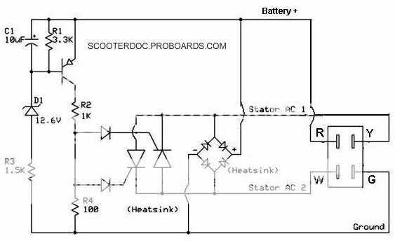
First, I found a wiring diagram that I believe applies to the insides of the GY6 R/R. I have altered it a little to match up with the modern wire color configuration:
The triangular shaped symbols are diodes and they allow electrons to flow in only one direction. Some of them, such as the larger two on the left of the diagram, also control voltage which allows the R/R to not only turn AC into DC for the battery, but turn all of the voltage supplied by the stator into approximately 12 volts. I have simplified the wiring down to the bare essentials with blue arrows showing the direction of electron flow:
Now it's important to remember that electrons are negatively charged particles and flow from negative to positive, so when testing with a multimeter the current flows from the black negative probe, to the red positive probe. This is exactly opposite of what a lot of people believe. But since this is the case, testing the diodes with the black on green gives no circuit with the red probe on the other three connectors, the electrons cannot move in that direction because of the diodes. This is evident on the charts below, green to any other connector with the black probe gives OL or Over Limit on the meter.
The same applies to any resistance testing with the black probe on the green connector, the electrons simply cannot get by the diodes as shown on the resistance chart.
Now if the concept holds true, we should be able to put the black probe on the red connector, and the red probe on the green and get values for both diode and resistance which we do as shown on the charts.
OK, so much for concepts, here are all the values that would register, the remaining showed OL because the diodes blocked the flow of electrons. The resistance tests are in ohms, the large M means mega or million ohms.
Resistance tests, positive is red probe, black is negative. So for example red probe on the green connector and black probe on the white gives a value of .912 M ohms:
And now the diode tests:
|
|
|
|
Post by Alleyoop on Nov 15, 2010 16:49:25 GMT -6
Rich,
AWESOME MY MAN!!! Add your tests and Photos as a New Thread to the Tech Section.
Alleyoop
|
|
Scooter Doc

Currently Offline
Posts: 1,936
Likes: 7
Joined: Jun 18, 2010 22:25:14 GMT -6
|
Post by sprocket on Nov 15, 2010 18:14:37 GMT -6
Super work doc!!
|
|
Doc's Anything Goes
Currently Offline
Posts: 2,739
Likes: 66
Joined: Oct 23, 2010 19:29:21 GMT -6
|
Post by tvnacman on Nov 16, 2010 16:59:29 GMT -6
Bash
Thank you for taking the time to do all of thoes measurements and for taking pics , the regulator that you have there is not correct for my application , I will see if I can exchange the regulator I have, in an effort to get the correct one .
|
|
|
|
Post by Bashan on Nov 16, 2010 17:27:19 GMT -6
Well guys, a scooter once again smacks that smug expression off of my face. John, I don't think it would work in my scooter either. By the way, I got to looking closer at the regulator that's been in my Bashan since the beginning and it has a large "FLP" stamped on the front just like yours. Anyway, I took the R/R off of my Bashan thinking all the tests would match up but they're not even close. In fact, I couldn't get one diode reading off of the thing. Thinking I might have ruined it somehow I put it back in the scooter, cranked it up, and checked all of the voltages. It's merrily charging the battery and cranking out 12v AC for everything else. It's dark, I'm baffled, and I can't think about until my brain quits hurting. The replacement I have matches up exactly on testing with the schematic I found, yet I'm scared to put it in my scooter for fear of frying it. This battle is for another day, I'm pooped. Rich
|
|
Doc's Anything Goes
Currently Offline
Posts: 2,739
Likes: 66
Joined: Oct 23, 2010 19:29:21 GMT -6
|
Post by tvnacman on Nov 16, 2010 17:51:25 GMT -6
ok we share the same problem what is the exact name and model of your scooter
|
|
|
|
Post by Bashan on Nov 17, 2010 12:10:33 GMT -6
This is the scooter I bought from Green Earth Scooters one year ago that has the FLP rectifier in it. The engine is a 1P57QMJ. It is manufactured by Bashan Aeronautical and the year is 2008.
|
|
Doc's Anything Goes
Currently Offline
Posts: 2,739
Likes: 66
Joined: Oct 23, 2010 19:29:21 GMT -6
|
Post by tvnacman on Nov 17, 2010 18:37:45 GMT -6
Bashin
the spare regulator you have will over charge your scooter. Try it if you want to I hear they blow the lights but you have to rev it up so do it slow with a voltage meter on it once you break 15vdc shut it down
|
|
|
|
Post by Bashan on Nov 18, 2010 20:20:28 GMT -6
Thanks for the heads up, I'm going to test my wife's rectifier, my rectifier, and the spare this weekend and see what the differences are. Then I might cautiously try the spare in my scooter and test with the multi and see what it does. I'll also get some pictures of mine that has the FLP on it and put it next to the oddball so folks will know when they order to at least have an idea of what it's supposed to look like. I also have a DC CDI in my Motorino that I'm going to test. I'll figure this out yet! Rich
|
|
Doc's Anything Goes
Currently Offline
Posts: 2,739
Likes: 66
Joined: Oct 23, 2010 19:29:21 GMT -6
|
Post by tvnacman on Nov 19, 2010 19:04:52 GMT -6
Bashin
I sent you a link to a regulator , the web page lists many different scooters . It listed one Bashin is it the same as your scooter ?
|
|


 ..BAD TO THE BONE..


