Clinician

Currently Offline
Posts: 40
Likes: 2
Joined: Apr 11, 2012 10:25:11 GMT -6
|
Post by rurc on Mar 3, 2014 12:08:02 GMT -6
Hello all. what I have here is a 45 minute upgrade that I feel anyone can do. This is simple and direct. If you can run a screwdriver you can do this with half your brain tied behind your back. Here is the scooter with the OEM headlamp bulb installed. 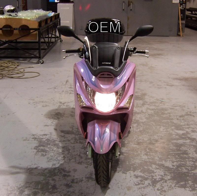 First thing you have to do is locate all the screws that hold on the front cowell of you bike. To make this easier I have photos of their locations. Please remove the front one last and install it first when going back together. 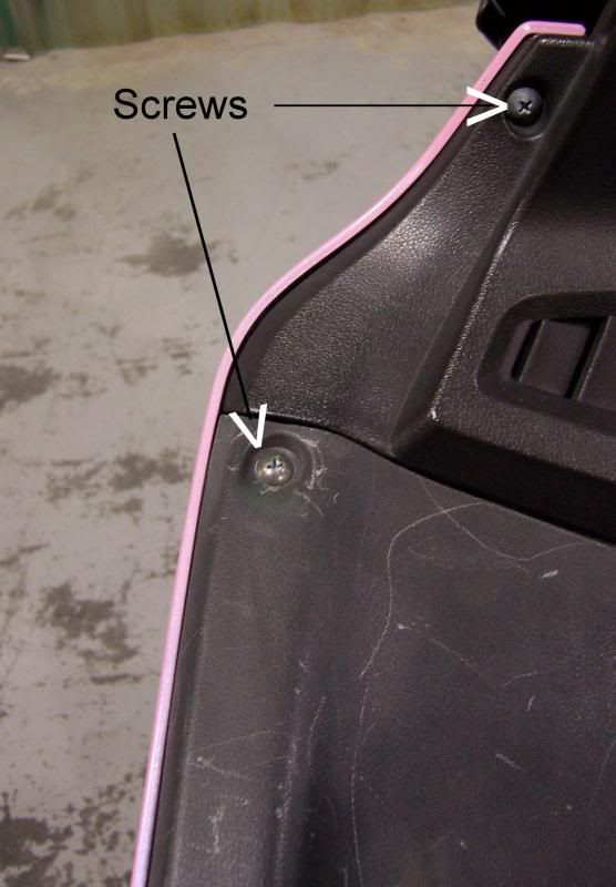 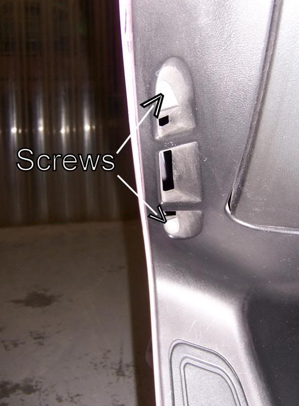 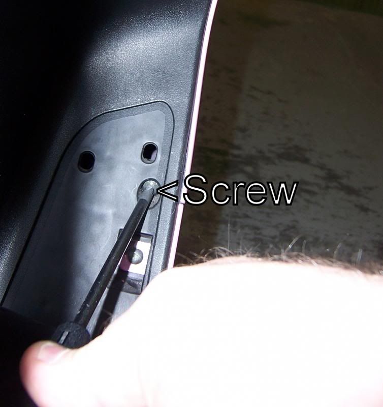 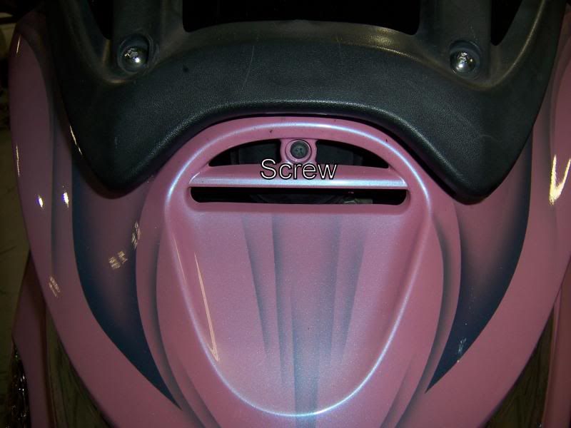 Be careful with the screws. I did brake one while tightening it too much. So use caution. Now unplug the harness and then take your headlamp assembly to a large bench to work from. So here is the back side of the cowell looking at the rear of the headlamp assembly. Here I have installed the HID bulb already but you get the idea. 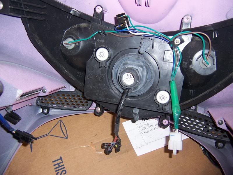 Here are the new and old bulbs going in and the next photo is of the wire harness that comes with the HID bulb. The bulb fits like a glove. 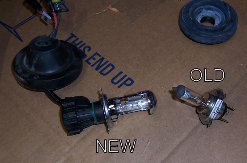 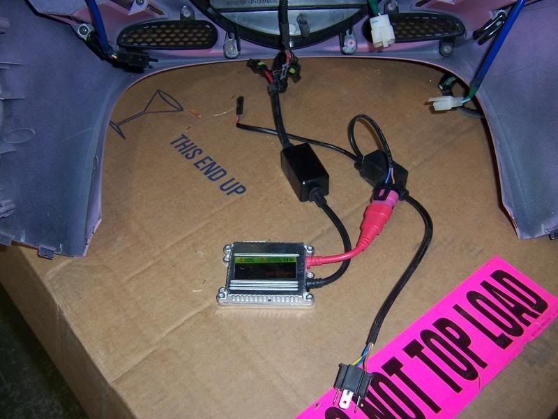 This is how I laid out the harness in the cowell. I had to try 3 different times to get it right. The sub frame parts on the bike kept on getting in the way so this is where everything ended up. 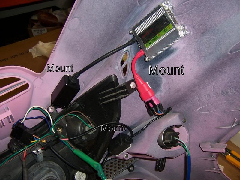 Here is the front view once reassembled. 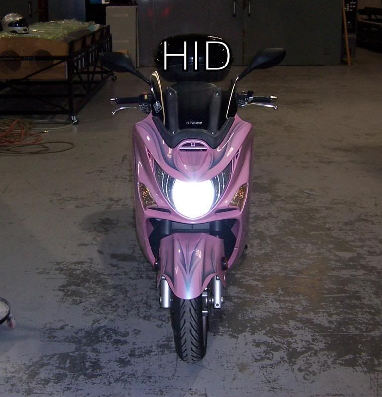 Now if you look here you will see the beam from old first then the beam from new. 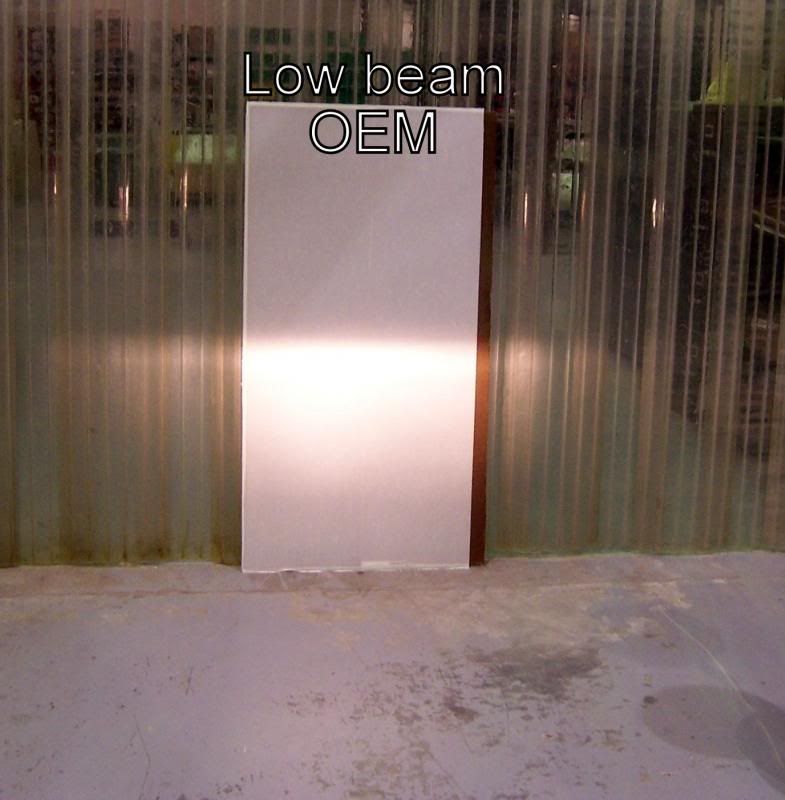 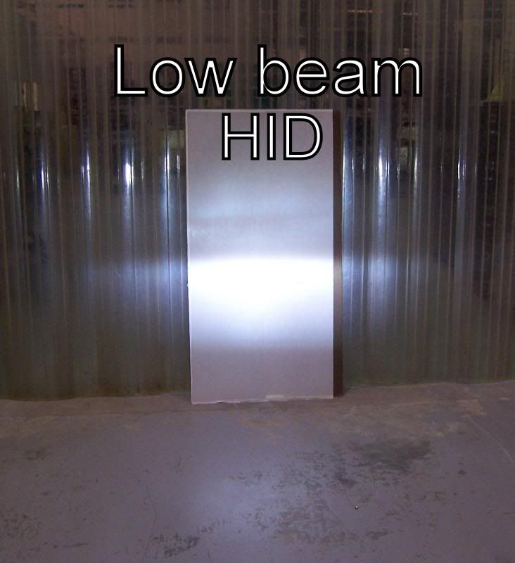 These photos were take about 45 minutes apart inside my shop at about 11am and 11:45am. Bright and sunny outside here in Florida and no lights on in the shop. all ambient lighting is from skylights. Here is the front view side by side.   Here is a link to the videos I shot both are less than 2 minutes. this is really a very easy install and the difference will be huge. I will post photos and videos during the night of the finished product. Forgive all the background noise I was running the oven during all this and it is noisy even more so with the heaters on. WORDS OF WARNINGFirst thing is to determine what your charging system can handle. If it is a small Chinese scooter or like that you may need to do more to make sure this does not damage your system. The best thing to start with is changing all other lights to LED. This will dramatically reduce the load seen by the charging system (mag).
Make sure when you change the turning signals you DO NOT use load equalizing resistors. NEVER use load resistors. These will eliminate any electrical advantage gained switching to LED's. If they wont flash on your bike then you have to change your flasher unit to an LED compatible unit. Some even have adjustable rates of flash. They are around $10USD on eBay.
If you have a weak system look for a 30 watt HID. Try to find ones that are Hi and Low beam in one bulb. You have to look and read the specs to be sure it is a dual beam. Most I have run into are not.Here is the euro style headlamp housing. 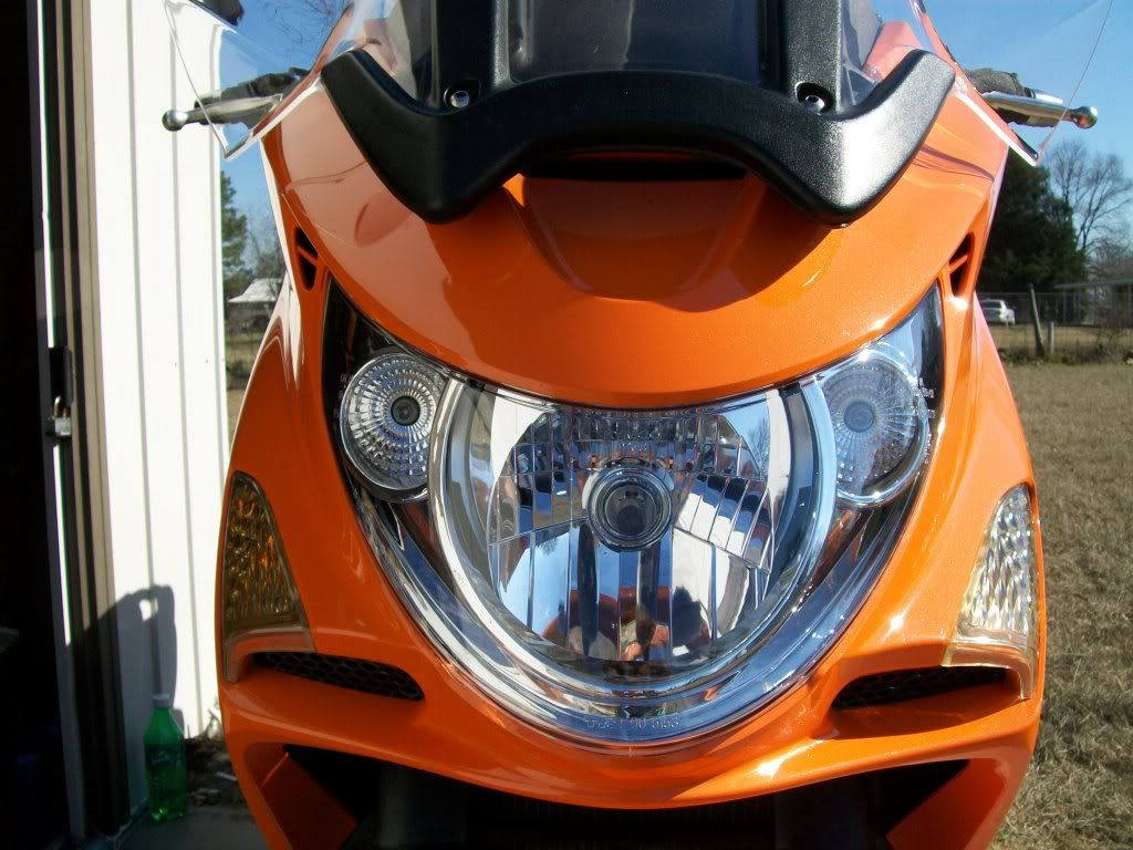 This is not my image. I am using it only to show the euro style headlamp housing. In any event have fun and do this upgrade to your bike. |
|
Clinician

Currently Offline
Posts: 40
Likes: 2
Joined: Apr 11, 2012 10:25:11 GMT -6
|
Post by rurc on Aug 2, 2012 3:08:54 GMT -6
|
|
Clinician

Currently Offline
Posts: 40
Likes: 2
Joined: Apr 11, 2012 10:25:11 GMT -6
|
Post by rurc on Jun 26, 2012 14:47:35 GMT -6
OK here I am again. Now I am testing the harness I modded. In the beginning I said that I had bought a second light fixture to experiment with. Well this second light fixture came with a full wire harness also. So I can modify it and not mess up my old harness so I can easily put this back to original if the need should arise. This first image is of the front of my scooter (CF Moto E-Charm) with the front radiator cover and front handle bar cover removed. I have labeled the 5 electrical hook ups that were connected to those body panels. Also before you unplug be sure you mark any similar plugs so they don't get put together backwards. These panels are not the easiest thing to remove (the handlebar cover) and you do not want to do it more than needed. 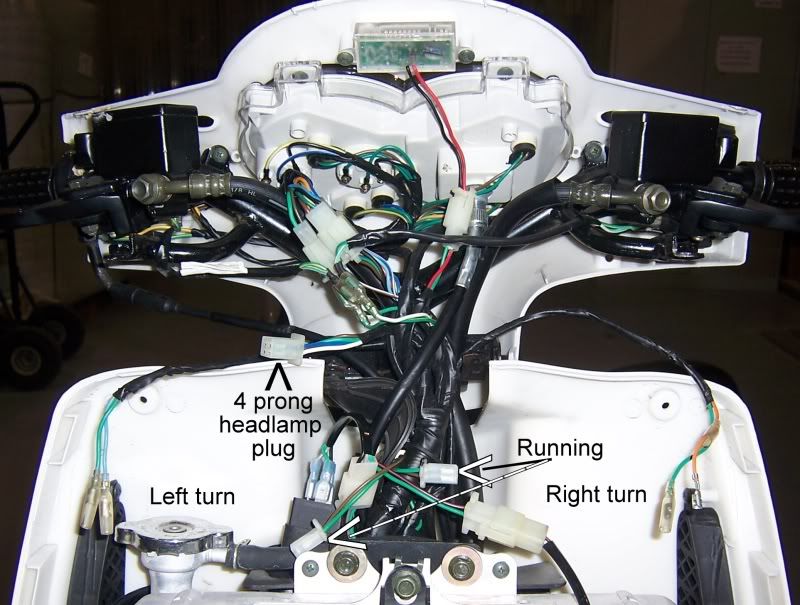 The next image shows the new harness plugged into the factory plug. Then this is hooked up to the HID wire harness. Nothing pretty here, just doing what it takes to get the test running. 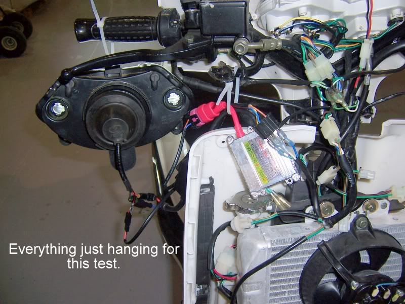 Here is the modded end of the headlight harness. Not much to it really. However I will have to find proper fitting connectors. I think I saw a H4 pigtail socket at Advance Auto parts. I will check on that after this damn almost hurricane is gone. 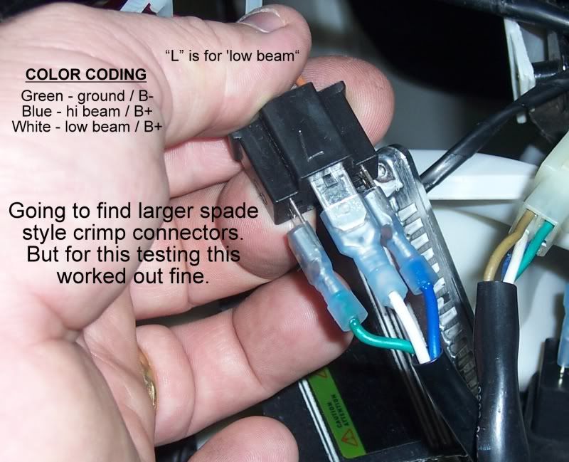 I also told you that I was going to change all the lights on the scooter to LED's. Well this is the first step. I have pulled the factory flasher unit (turning signals) and tossed it. I got a digital flasher unit that will run LED's or regular bulbs and replaced the factory one. I took the unit and sealed it up with RTV silicone. For some reason the only way you can install this is with the connector end up, right where it can collect water. So what ever you buy for yours make sure it is sealed from the elements. 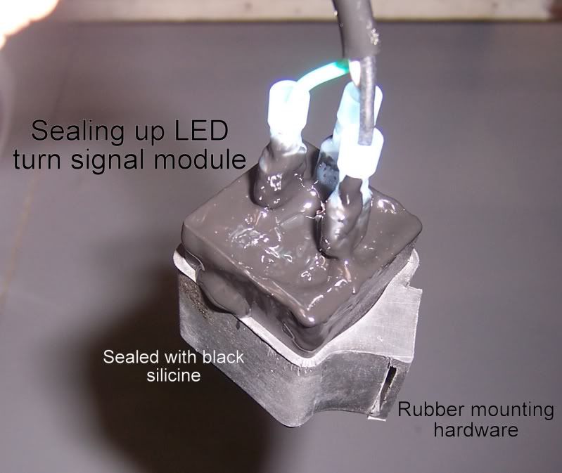 Here is the flasher module in the factory location. I was able to use the factory mount. 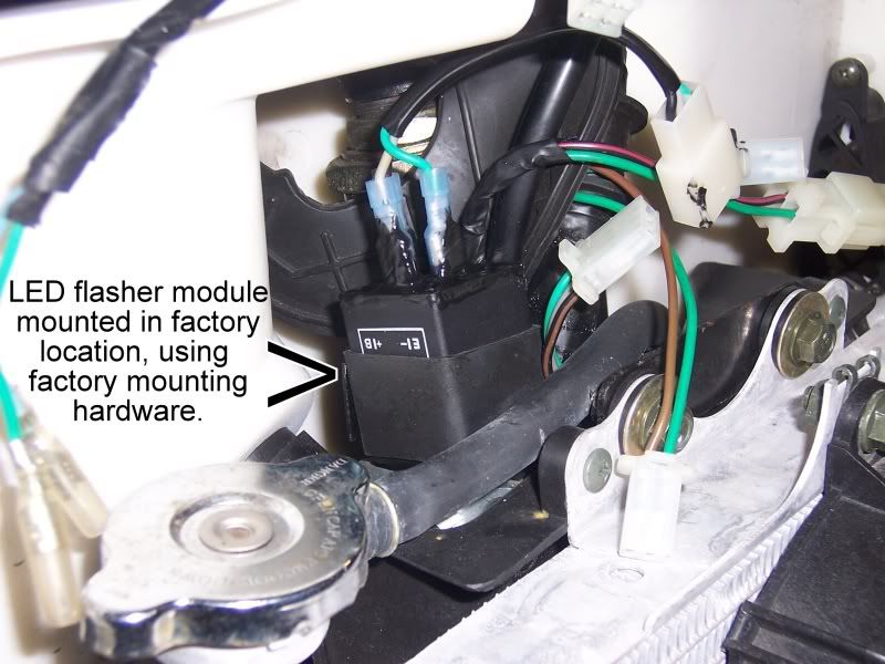 Finally here is a short video of the scooter running and the light working just perfectly. The next installment should be the full modification of the switches and then the installation of the light. Thanks for watching and talk to you soon. |
|
Clinician

Currently Offline
Posts: 40
Likes: 2
Joined: Apr 11, 2012 10:25:11 GMT -6
|
Post by rurc on Jun 21, 2012 15:12:49 GMT -6
Glad it is vented... it is a CFMoto, better build quality too.....but most units aren't vented and that housing is superior to the average Chinese GY6..it is also considerably larger. I'm just recommend that people need to consider heat and venting , or you will have a melt down... You are 100% correct. Better safe than sorry. I did do a longer test just look above.  |
|
Clinician

Currently Offline
Posts: 40
Likes: 2
Joined: Apr 11, 2012 10:25:11 GMT -6
|
Post by rurc on Jun 21, 2012 15:11:13 GMT -6
OK I did a longer bench test today. I did it for 50 minutes but the battery died on my camera at just over 30 minutes and I did not realize that. In any event this thing ran flawless. The temperatures were a little hotter. The hottest place I could find on the lamp was 138 0 F. The housing right where the bulb mounted was seeing 131 0F. At no place have I found any melting or deformation. The front lens got as hot as 122 0F. I know that these temperatures are rather hot as just a temperature but I dont see this being a problem for the housing. Remember this is sitting stationary on a shelf with NO moving air of any kind. Well here is the time lapse video. I charged the little battery fully and the start voltage with NO load was 13.1 VDC. If you look on the right side of the video you will see a voltage meter (yellow) and a amp meter (gray). You will see the amp draw go from over 5 to under 4 at the end. It is really hard to see the volts and amps but I swear that they are there.  I am sorry that the camera did not record the entire hour but what can I say. |
|
Clinician

Currently Offline
Posts: 40
Likes: 2
Joined: Apr 11, 2012 10:25:11 GMT -6
|
Post by rurc on Jun 19, 2012 14:23:30 GMT -6
Very nice work....I installed 35w...HID's...5000k....H4..Bi-xenon....Hi/Lo's...superslim ballast in my scoot last year and love the mod...enjoy the ride.... I am going with a 6000 0 Kelvin myself. I like the whiter with the touch of blue to help prevent glare. |
|
Clinician

Currently Offline
Posts: 40
Likes: 2
Joined: Apr 11, 2012 10:25:11 GMT -6
|
Post by rurc on Jun 19, 2012 11:03:19 GMT -6
Hey Rurc, what kind of manuals do you write? Wonderful looking tutorial, I do appreciate it. Rich
Well some of my favorites were the factory technical repair manual with troubleshooting for Lamborghini Diablo and Jalpa. Factory repair and replacement of complete wire harness for Audi North America on TT and A8L. There are others for Porsche. But these were back in my days as a master gilded tech for all the above makers. Now that I work in aerospace I have done everything from airfoil design and manufacturing to safety documents for OSHA. So most likely nothing you have had to read. Fairly dry reading. ;D |
|
Clinician

Currently Offline
Posts: 40
Likes: 2
Joined: Apr 11, 2012 10:25:11 GMT -6
|
Post by rurc on Jun 19, 2012 10:51:14 GMT -6
I would ventilate that housing....15 minutes isn't realistic for my night rides. Seen the lenses yellow in couple of weeks from the heat and melt completely... Not that particular lense, but you need to extend your testing to an hour or so for the real world, or just take short trips... ;D I see your point and I will do a longer bench test but let me give you my thought process in deciding on the 15 minutes. First: I figure that chances you will be riding not sitting still with the light on. When you are riding you get a tremendous amount of cooling flowing across the surface because of the air flow. This is the principle that a radiator works and those work very well. During this test it was on a shelf that was only open on one side. It was not air conditioned. There was NO fan running supplying any circulation of air. I am in Florida and the atmospheric temperature was 89 degrees F. Second: I felt that 15 minutes should allow maximum saturation based upon the thickness of the plexi being used. If I were putting that same thickness of plexi in my oven to heat it for forming that is a little more than the time I would give it to heat up through out the material. Third: The housing is ventilated (see the image below) 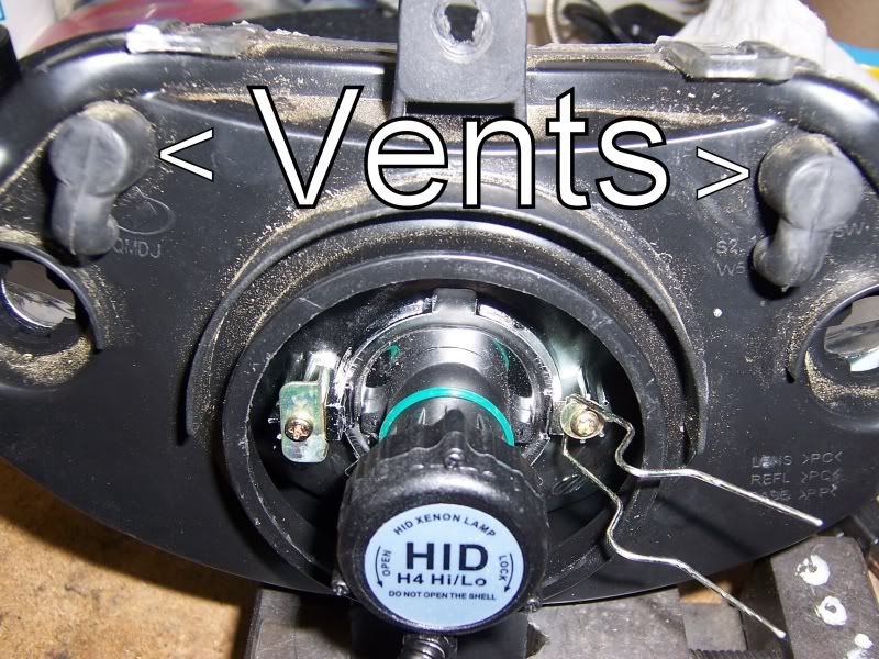 But I would not be opposed to more vents. You have to be careful with vents in headlamp housings because they can introduce moisture and that will cause blown headlamp bulbs. Fourth: I am really more concerned with the LED I will be running as daytime running lamps because they are 7 watt with very limited heat sinking. All the above said I will run a longer bench test just to really set this and check. This will give me a chance to use my time lapse app for my iPhone, cool. |
|
Clinician

Currently Offline
Posts: 40
Likes: 2
Joined: Apr 11, 2012 10:25:11 GMT -6
|
Post by rurc on Jun 19, 2012 10:26:53 GMT -6
when I click on the 2 videos I get ........... "this video is private" Oh man I did not know. OK I have made both files public. I cant tell if it worked so please check them and see if that worked. If not I will work it from a different angle. Sorry for the problem |
|
Clinician

Currently Offline
Posts: 40
Likes: 2
Joined: Apr 11, 2012 10:25:11 GMT -6
|
Post by rurc on Jun 16, 2012 8:38:22 GMT -6
OK We are back for another installment of the HID install. Well we had finished making the bulb fit into the housing and now I want to test all the electrical and check the beam and any temperature issues, so here we go. In this image you will see my bench lay out. I only labeled 3 things (if you cant tell the batteries from the meter to the headlight housing you should be paying someone to do this for you) 1) the ballast, 2) voltage stabilizer, and 3) Hi/Low relay.  I am running the light through my meter because even though the lamp is rated at 35 watt (2.4 amps at 12.5 VDC) I know that this is going to pull more than that from experience. So I want to know exactly where we are going to be. I will be comparing this to the factory bulb so I can run my numbers so I can be sure that I will not over load the system as a whole. At the start I checked my battery voltage and with no load on the little batteries I was using for the test the voltage was 12.2 VDC. So the batteries are under charged. This will cause a higher current draw but I can calculate that out in the end. During the test I checked the voltage and before I shut it down it had dropped to 11.1 VDC. At 11.1 VDC the current draw for a 35 watt bulb should be around 3.2 amps, without the servo for the HI beam engaged. Below is a 2 minute video with a start up and quick run down. the changing light pattern you will see during the video is not the bulb. Yes the bulb does get brighter over the first minute or so but what you are seeing in the video is the camera trying to adjust for the change in intensity from the bulb. This is a 2 minute video. The video below is 1 minute 30 seconds and it is after the lamp had been running for about 15 minutes. I know I say 10 minutes in the video but I am wrong. Here is where I tell you about the voltage drop on the batteries and a couple of other things. OK the following images tell the story about temperatures on parts of the housing and electrical parts. 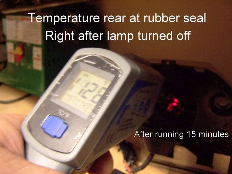 Sorry the next one is blurry. I try not to use a flash if I am showing a screen. 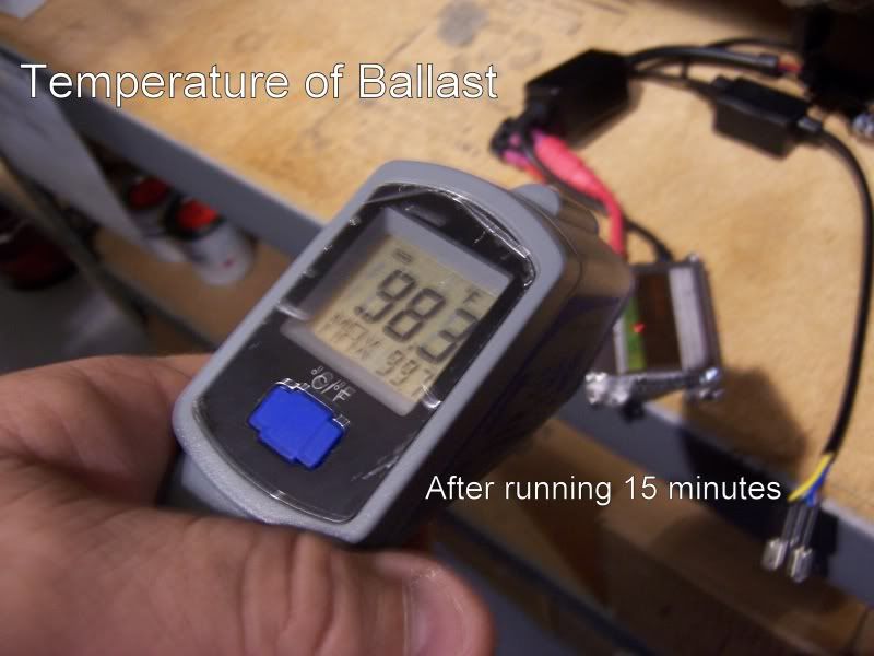 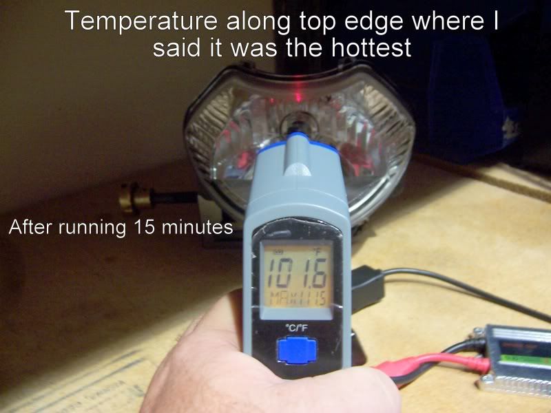 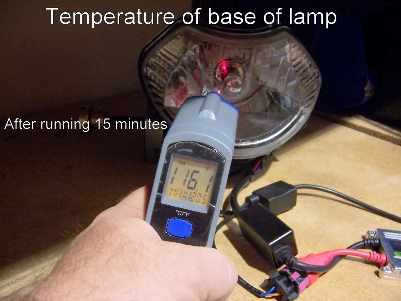 Next installation of this guide will be taking the test set up outside and looking at the beam at night. The update after that will be changes to the factory headlamp wire harness. Just the harness that is directly hooked up to the headlight housing not the main harness. The main harness will come later. Until then keep it safe everyone. |
|
Clinician

Currently Offline
Posts: 40
Likes: 2
Joined: Apr 11, 2012 10:25:11 GMT -6
|
Post by rurc on Jun 15, 2012 10:32:42 GMT -6
Wow man, fantastic! Thanks for posting and the beautiful pics. I opened this thread up thinking somebody was asking for help and got a great big present.  This one's headed to the tech library when your all done and everybody's had a chance to ogle it. Rich This one's headed to the tech library when your all done and everybody's had a chance to ogle it. Rich Thank you Rich. Seeing that I have written some of the longest technical manuals in history (in my belief) I can do these things with my eyes closed now. I dont know why the messing image will not show above but here is a link to it. s143.photobucket.com/albums/r135/RURC/Images%20for%20blogs%20and%20builds/?action=view¤t=08frontviewoflampinstalledinhousing.jpgI have tried everything to get it to work but it will not. I even deleted it from Photobucket and then reloaded it and the exact same thing happened. Oh well the link works |
|
Clinician

Currently Offline
Posts: 40
Likes: 2
Joined: Apr 11, 2012 10:25:11 GMT -6
|
Post by rurc on Jun 14, 2012 23:30:51 GMT -6
First I wish to thank everyone that gave advice on my coil problem I had. This will be a step by step guide with photos giving very complete instructions as to everything I do (including mistakes) in this process. I am writing this as I do the job. So you may see parts and then a few days may go by before I get more done and up date. This in going to be more than just a simple plug and play. Doing the HID will be the wiring challenge. You don't want HID lights to get shocks to their voltage systems. So since my E-Charm runs the head light all the time that will be a problem. There is not switch for the headlight. So my plan is to take the 2 light that run on the same wire harness as the headlight and change them into day time running lights. I will get 2 x 7 watt LED 194 style lights and wire them separately. Right now the E-Charm has a switch that will turn on and off the running lights. What I am going to do is wire that switch to turn on and off the new HID light. Then the other lights, as well as the 2 x 7 watt daytime running lights will be wired to always on. The HID is 35 watt (bi xenon). At the same time I will also be changing all lights over to LED's.The total wattage usage after the change is complete will be less than how it was originally. I have bought a used headlamp assembly to test the HID for melting, beam pattern, and fitment. I do not know all the other scooters that use the same light set up as the E-Charm. But the CF Moto V3 and V5 and the Q-Link scooters also use this same light. I am sure there are others. Any how lets get started; I have done my research and learned a lot about HID and the supporting electronics they have. First when buying your system make sure the ballast is an AC type. Since we are dealing with a rather low power system AC output ballasts are much more stable voltage wise to the bulb. thus making the bulb and the ballast last much longer. I found mine on eBay for less than $40.00 complete with very good water tight connectors. Any how here is how it arrived:  Once opened: 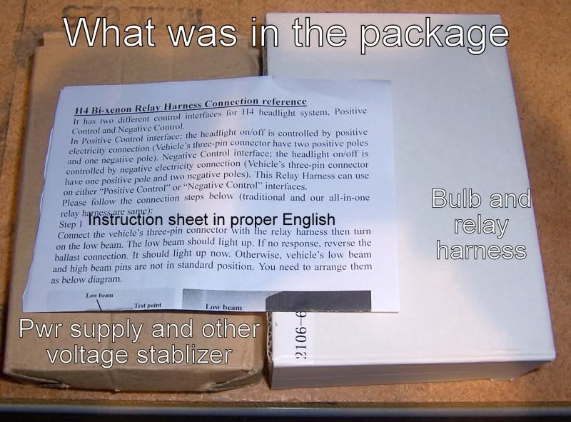 All the parts from the package: 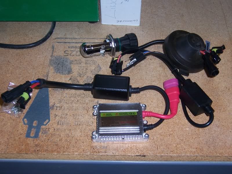 Close up on ballast: 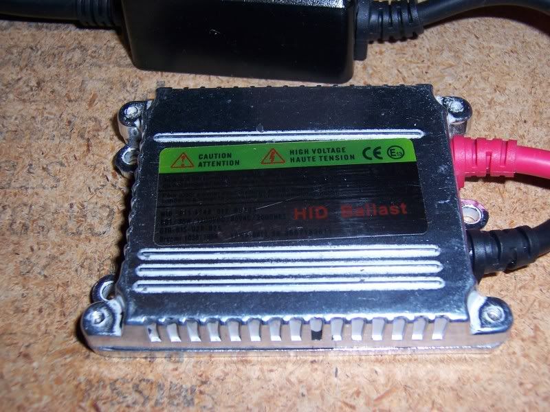 Close up of just lamp / bulb: 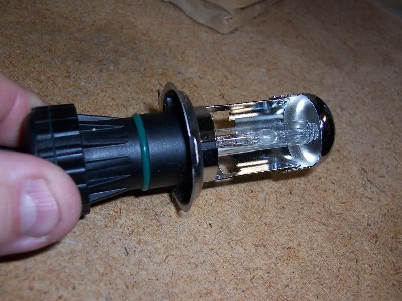 The following images are all done on the bench with a second Headlight assembly I have. Lets get a good look at the housing: 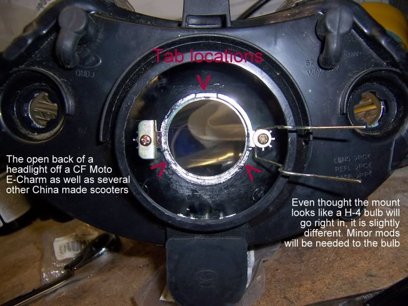 Modifications: 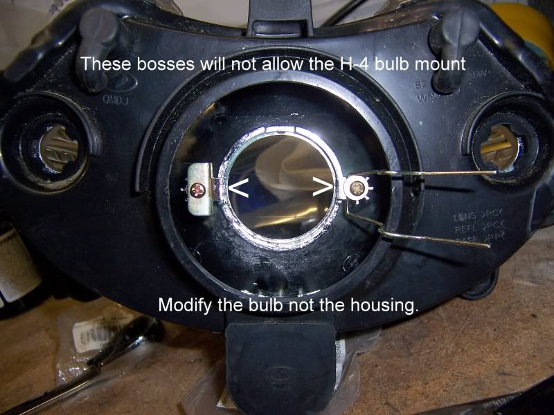 Like I said above an H-4 is a very close fit but not perfect. Align the bulb with the large tab up and line that tab with the top notch on the housing. In the above image there are arrows pointing to the biggest problem. Using a marker indicate where the trim points need to be on the bulb. Do NOT trim the housing. This WILL violate the structural integrity of the retaining clip. Mark as shown: 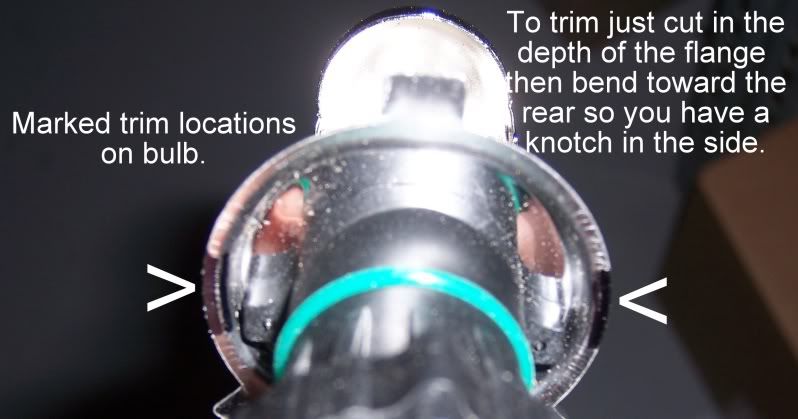 To make the notches in the bulb I just used a good quality side cutter pliers and cut the flange on the bulb just to the first bend, about 1/16 of an inch. Once I cut both sides (4 cuts) I then used a pliers and bent the area between the cuts I just made and bent the flange up toward the rear of the bulb. Note that the bulb will not sit down into the recess. This will not be an issue in later steps we will seal this. 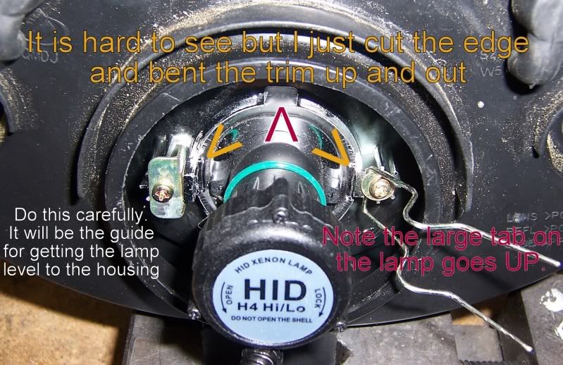 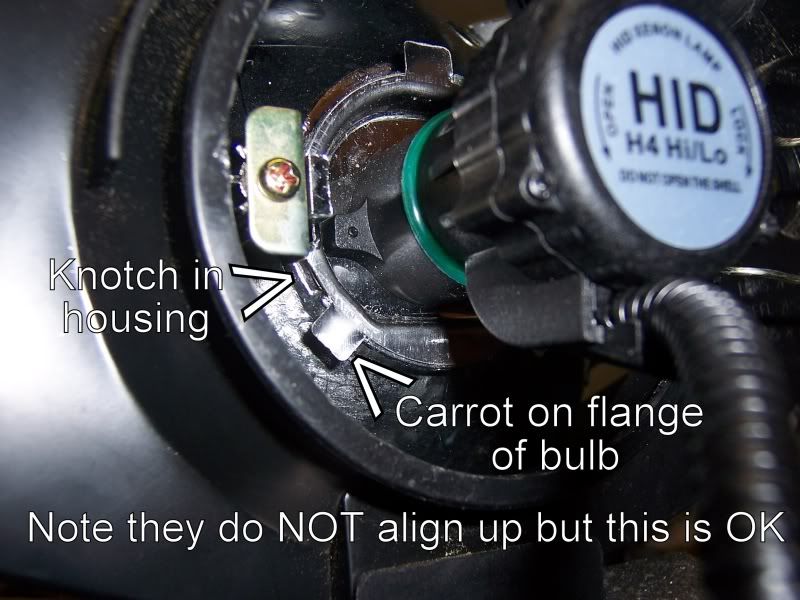 Once you have all this in line, using the existing locking wire lock the bulb in: 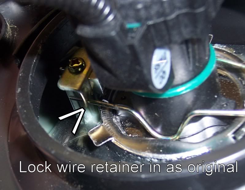  Look at this now from the front:   The next update will be the wiring and bench testing the light. |
|
Clinician

Currently Offline
Posts: 40
Likes: 2
Joined: Apr 11, 2012 10:25:11 GMT -6
|
Post by rurc on Jun 5, 2012 22:36:42 GMT -6
 ride on..great news! I did all LEDs a few years go..they are straight plug ins..on the HID you should be OK , but many go from an 8 coil stator to 11 coils to drive them...I think there are 35 watt kits , so I suggest you go with those rather than trying 55 watts... You will need resistors in the flasher circuits if you use LEDs there my be issues with the HIDs ...they run very hot and melt the plastic lens...depends on the style... just a heads up Yes the basic LED change over would be just plug and play if that was all. But I cant do that. The change over to LED's will not include resistors. The reasons I want to go to LED's are; 1 their faster on time is great for safety, 2 brighter with less power usage, 3 take load of the charging system. Now adding resistors is not a smart thing to do. One if you exactly match the resistance of the original lamp you may as well just keep the original light bulb. The addition of the resistor takes away the benefit of lower wattage draw. Think about it. There will special circuitry made to electronically flash the LED's Doing the HID will be the wiring challenge. You dont want HID lights to get shocks to their voltage systems. So since my CF Moto runs the head light all the time that will be a problem. There is not switch for the headlight. So my plan is to take the 2 light that run on the same wire harness as the headlight and change them into day time running lights. I will get 2 x 7 watt LED 194 style lights and wire them separately. Right now the CF Moto has a switch that will turn on and off the running lights. What I am going to do is wire that switch to turn on and off the new HID light. Then the other lights, as well as the 2 x 7 watt daytime running lights will be wired to always on. The HID is 35 watt (bi xenon). The total wattage usage after the change over will be less than how it was originally. I have bought a used headlamp assembly to test the HID for melting and beam pattern. This is not going to be your standard work up. |
|
Clinician

Currently Offline
Posts: 40
Likes: 2
Joined: Apr 11, 2012 10:25:11 GMT -6
|
Post by rurc on Jun 5, 2012 14:29:05 GMT -6
I am looking at buying a SunL SL250-22. It is a 2008 with less than 2000 miles. Now I know that this unit needs work. I have been told that the stator and coil are for sure bad and need replaced. This is what the mechanic told me in the shop that it was serviced at and taken to to get fixed. The owner did not have the money to fix it and pay the mechanic. So the owner took it back non working. Here is what I am concerned about. I have been told that SunL is out of business. Is this true? I have not been able to confirm this. Also I have heard both that SunL are good bikes and that they are crap. I welcome your opinions. 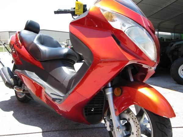 |
|
Clinician

Currently Offline
Posts: 40
Likes: 2
Joined: Apr 11, 2012 10:25:11 GMT -6
|
Post by rurc on Jun 5, 2012 13:58:10 GMT -6
GREAT NEWS
Everything has been fixed. Was finally to trace everything to the coil, including the pushing on the handle bars to get off of center stand. The coil was going inop once it got hot. Then found the wire supplying ground to the coil had broken internally. So it was 2 different problems, like I thought, but they had one common fix. I have replaced the coil (took a long time to get) and have made a vent in the rear panel of the foot well to keep all this cooler. Now I am going to start a thread on a full on upgrade to all LED lights and HID headlamp. This will require a lot of wire harness mods.............
Thank you to everyone that made any comment
|
|


 This one's headed to the tech library when your all done and everybody's had a chance to ogle it. Rich


