Doc's Anything Goes
Currently Offline
Posts: 371  Likes: 18
Joined: Jun 13, 2014 16:48:23 GMT -6
|
Post by glavey on Aug 8, 2014 18:50:14 GMT -6
I modeled and printed a mount for the pump. It'll hold the pump to the frame with zip-ties or hose clamps if I discover that the zip-ties aren't good enough. 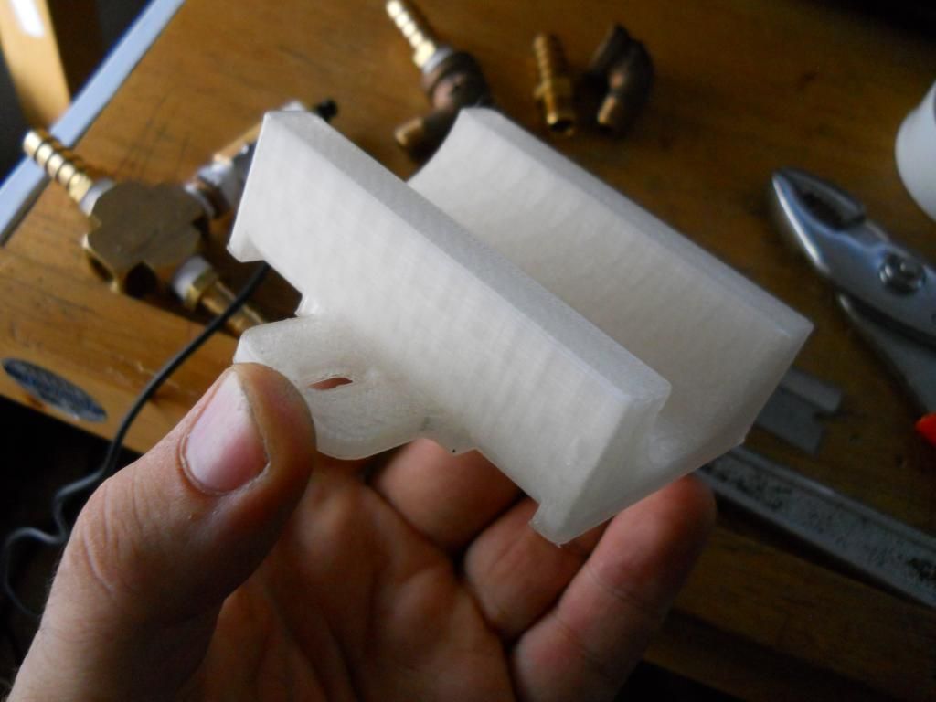 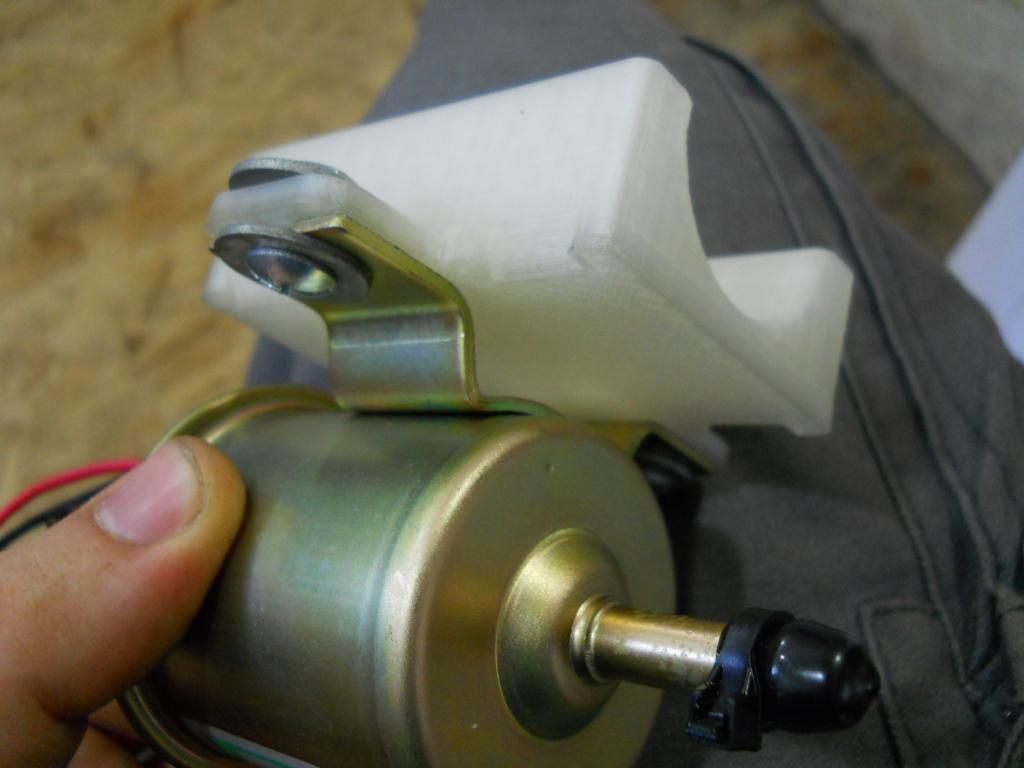 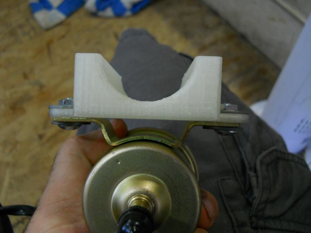 Here it is attached to the scooter's frame in its hopefully final location: 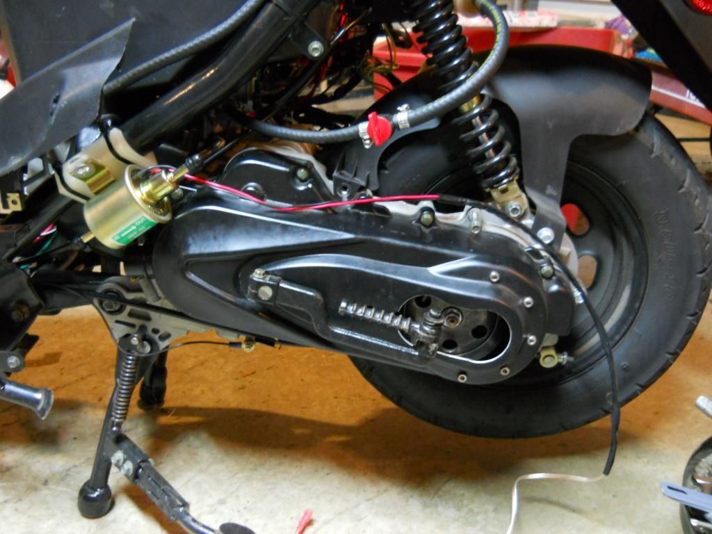 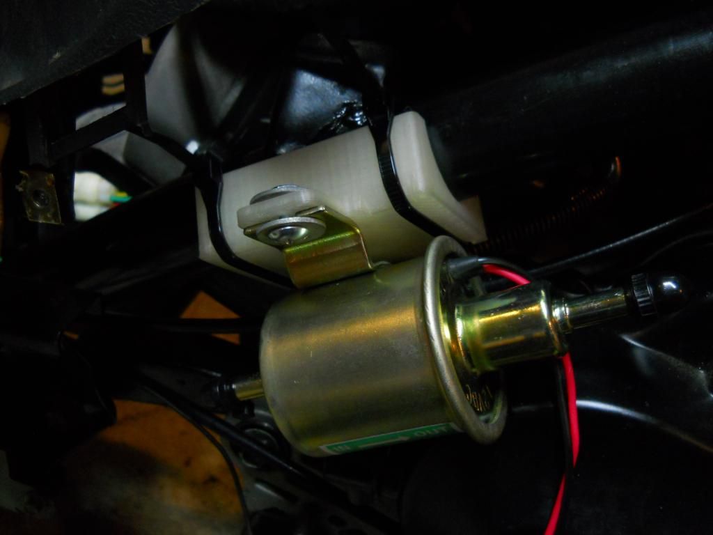 The protruding lip on the pump rubs against the cvt cover. I'll have to do something about that, possibly a small piece of foam or some silicone. 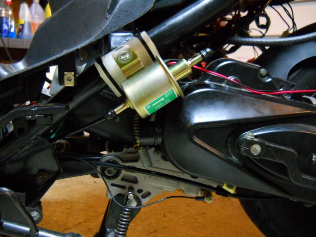 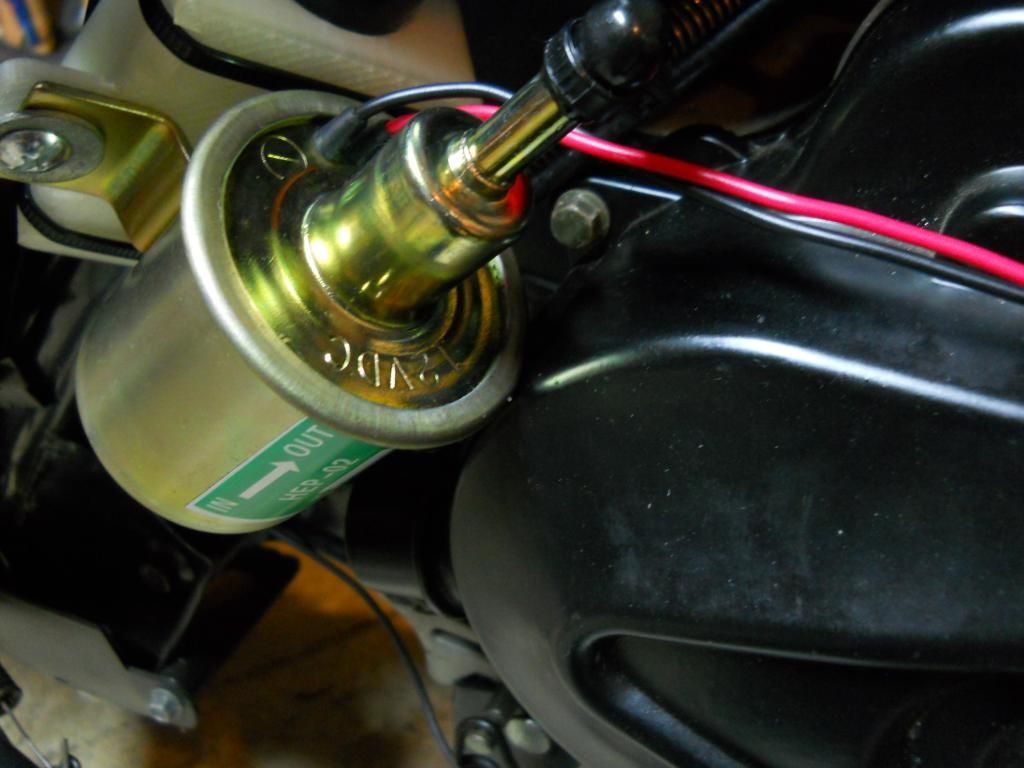 I have two different hoses to use for the cooling loop; one that came with the radiator that doesn't have a brand name, but is thicker; and one that I bought from carquest that is thinner but is made by gates. They look like they have the same internal diameter. 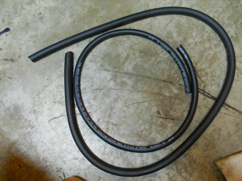 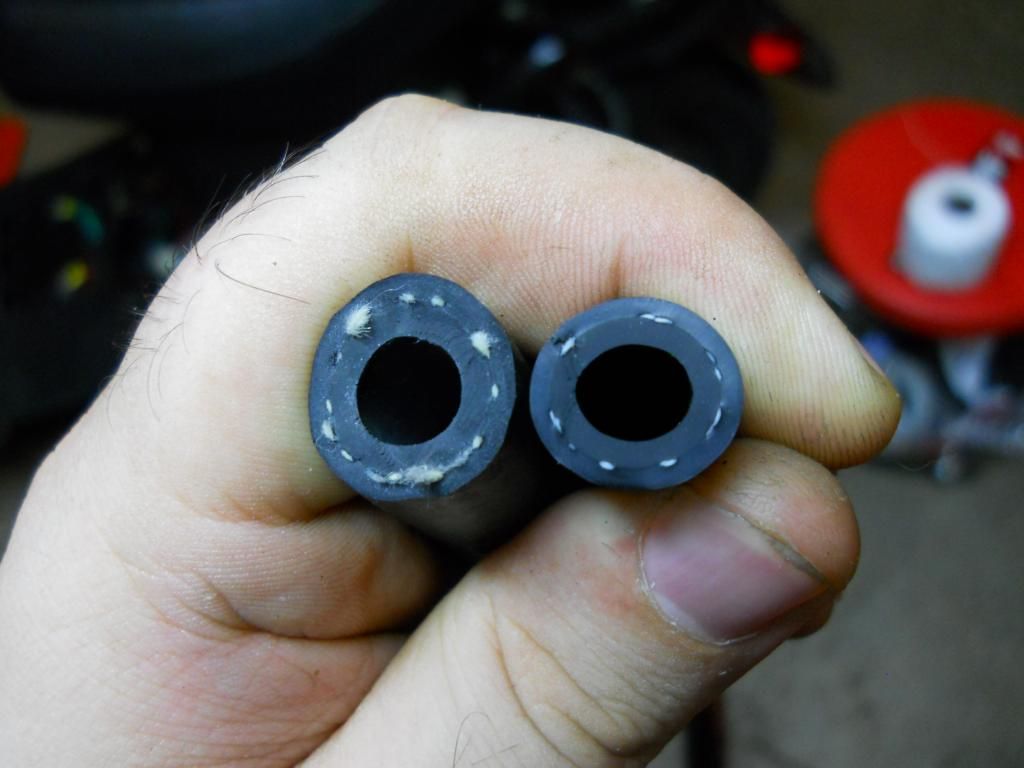 The temperature probe I am going to use requires the probe be grounded through the metal body of the probe itself, it doesn't have an embedded ground wire. Since I am going to use it in the 4-way fitting which will be electrically isolated from the frame ground, I needed to somehow connect the probe exterior or one of the fittings attached to it to ground. I have a HUGE soldering iron that I inherited from my grandpa; 200 watts and a tip as big as my thumb that I used to solder a wire to one of the fittings that will connect to the probe. 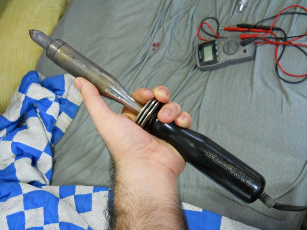 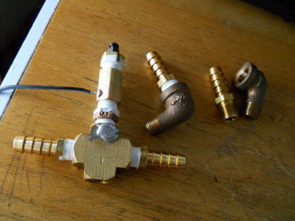 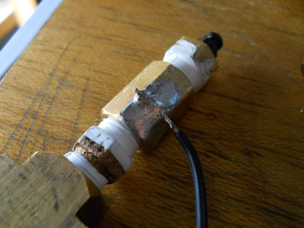 First I tried soldering on to the 4-way fitting, I could get the solder to melt on it, but not "flow". It had too much thermal mass. Next I tried the female-to-female coupling, that worked well. I could get the solder to flow onto the fitting by itself. I added some strain relief in the form of a generous glob of silicone. The silicone I used is rated for temperatures up to 400F, so it will be just fine. On a side note, silicone does not stick well to solder. 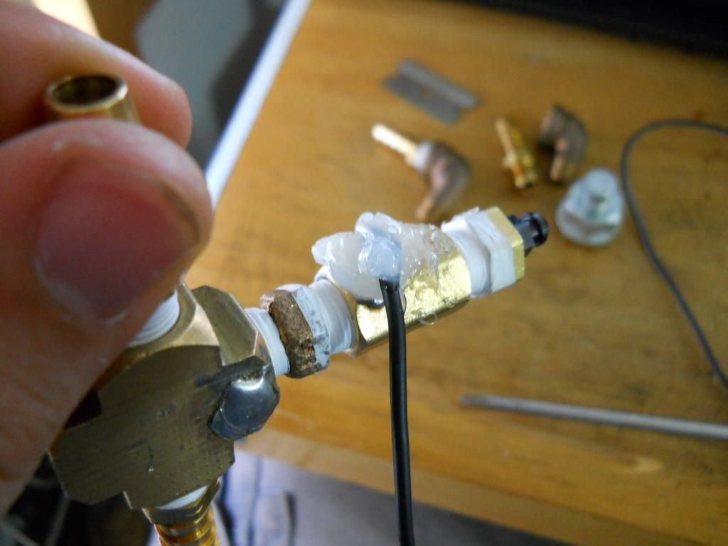 I tested the resistance from the hose barbs to the bleeder valve; 0.1 ohms, essentially a dead short. Tomorrow, draining the oil from my scoot, fitting the probe to the 4-way, and drilling the hole in the valve cover (EEEKKKKK!!!) for the "add-a-drain", and finding a mounting solution for the 4-way and the radiator. Bashan, if you see this before I start tomorrow, is there a place in the valve cover that I should or shouldn't drill into? I'm quite certain I shouldn't mess with the breather labyrinth, but there isn't much room between that ans the sides of the cover. |
|
Doc's Anything Goes
Currently Offline
Posts: 371  Likes: 18
Joined: Jun 13, 2014 16:48:23 GMT -6
|
Post by glavey on Aug 8, 2014 12:15:15 GMT -6
Small update: I mocked up the locations of the radiator and the pump. The pump is going to be quite easy to mount. The radiator, however, is another story. 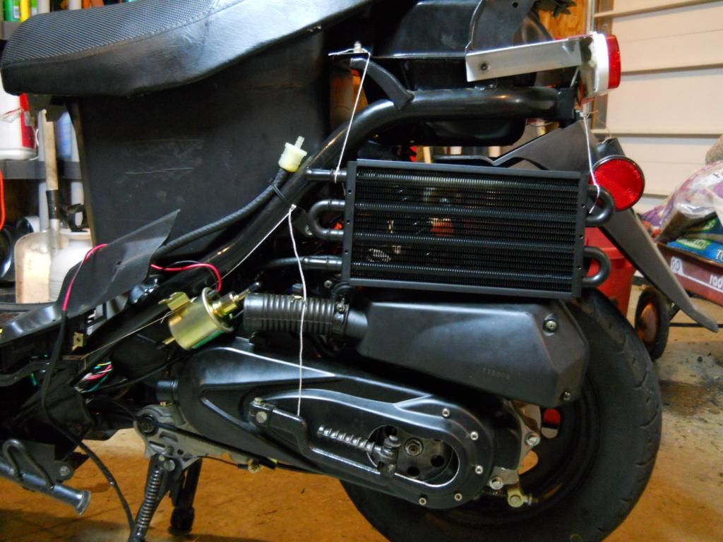 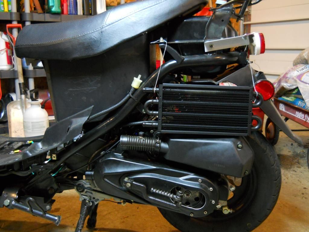 The rear mud flap, reflector, airbox, fuel line, filter, shut-off valve, and frame cross-member are all in the way. I can cut away the parts of the rear mud flap that are in the way, as you can see here: 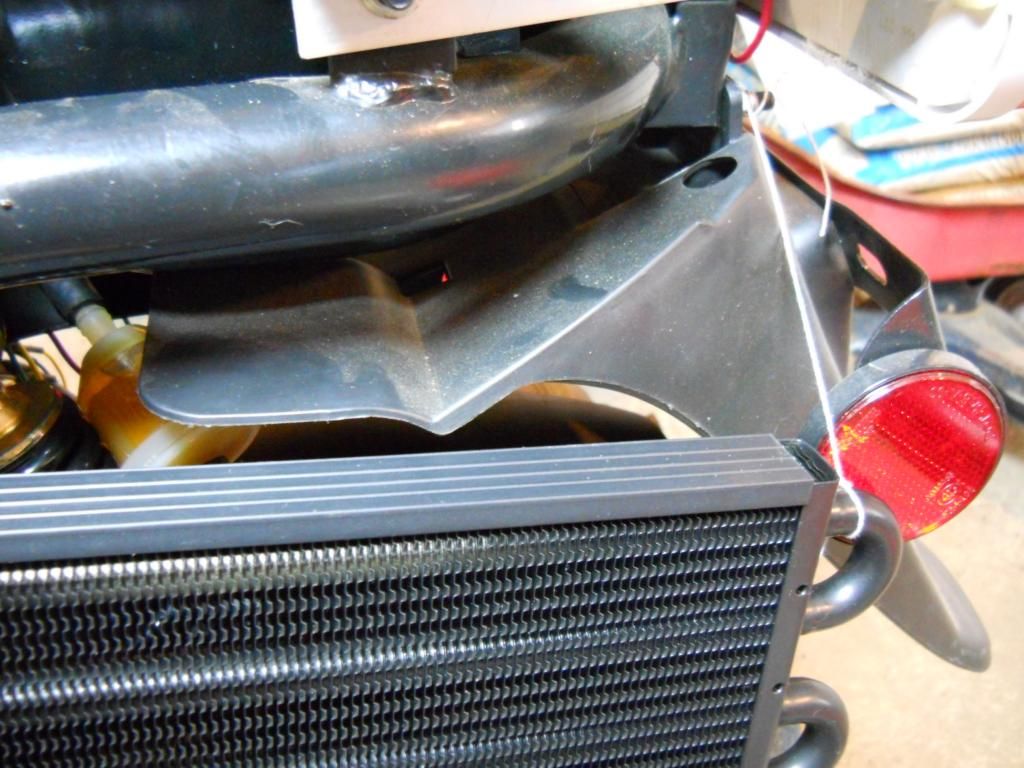 I can route the fuel line coming from the tank down under the rear part of the seat and the frame cross-member. I then realized that if I removed the stock airbox and installed a pod filter I have: 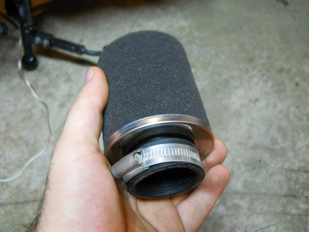 I would have tons of room right where I need it. Here you can see the airbox removed, my fuel lines, and the radiator mocked up: 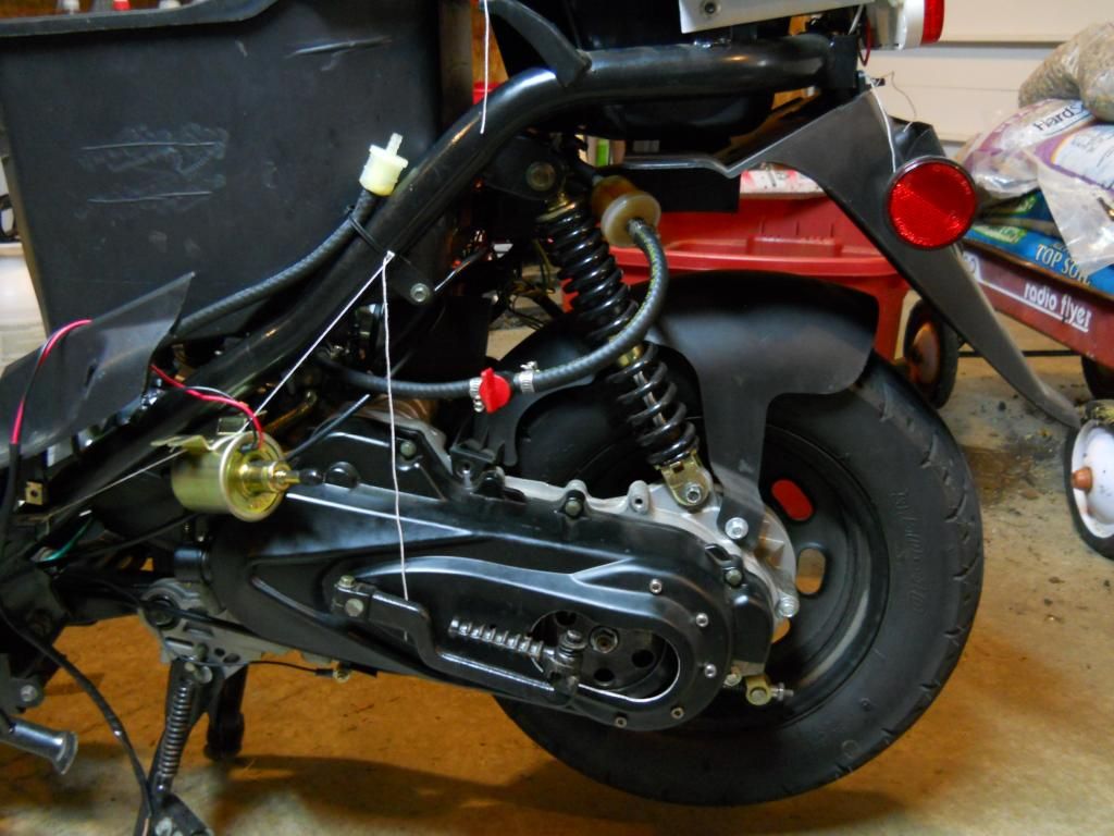 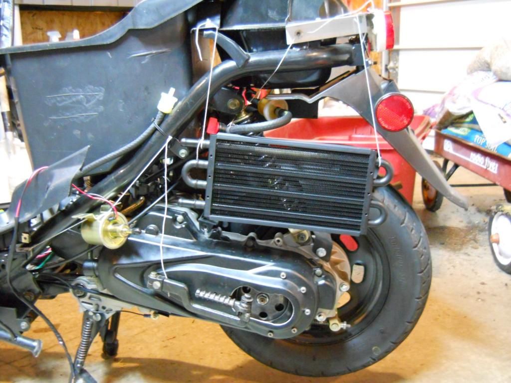 I am trying to keep my scooter as quiet as possible, that is the reason I have the stock airbox and muffler still installed. Also, I have read that these carburetors like some distance between where the air is sucked in and where the assembly is attached to the carb. However, it will be so much easier to mount the radiator with it out that I may just have to live with the noise and tune the carb to the best of my abilities. If you look here: 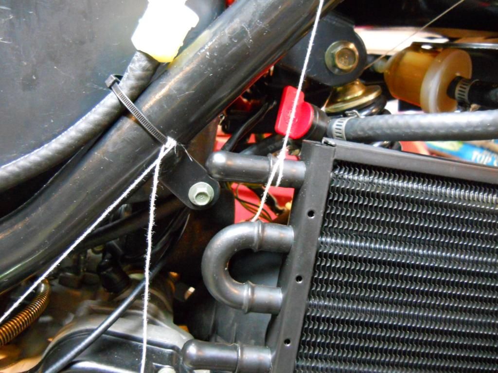 you can see that the upper radiator barb is right next to the frame, and that is where I need to put the 4-way fitting for the temp probe and bleeder valve. I could zip-tie the fitting to the frame (I do believe that zip-ties rival duck tape in usefulness) and put some foam between the fitting and the frame so they don't rub on each other. I could also drill a few holes in the bucket seat and zip-tie it there, but I'm not sure what at what temperature the plastic will start to melt and it is a structural, load-bearing part. Also, I would like to eventually cut the bucket part out and make a some metal framework to attach the seat to the scooter frame. Mounting the radiator in place is going to be a bit tricky, but in the end I think it is doable. In the picture above, you can see that there is a tab on the scooter frame where the petcock usually is; I can bend a piece of metal from there to the back of the radiator and screw or zip-tie it to the small holes you see at the end of the radiator. I can do something similar here: 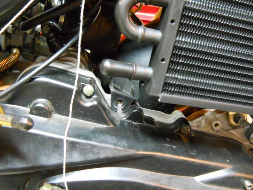 with the vacant bolt hole to the left and the bottom of the radiator and well as here: 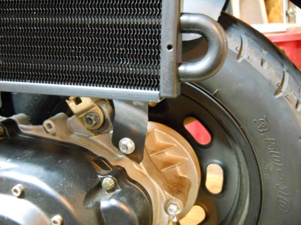 with the bole hole just behind the shock mount and the bottom of the radiator. Holding the top right of the radiator is going to be a little more involved; 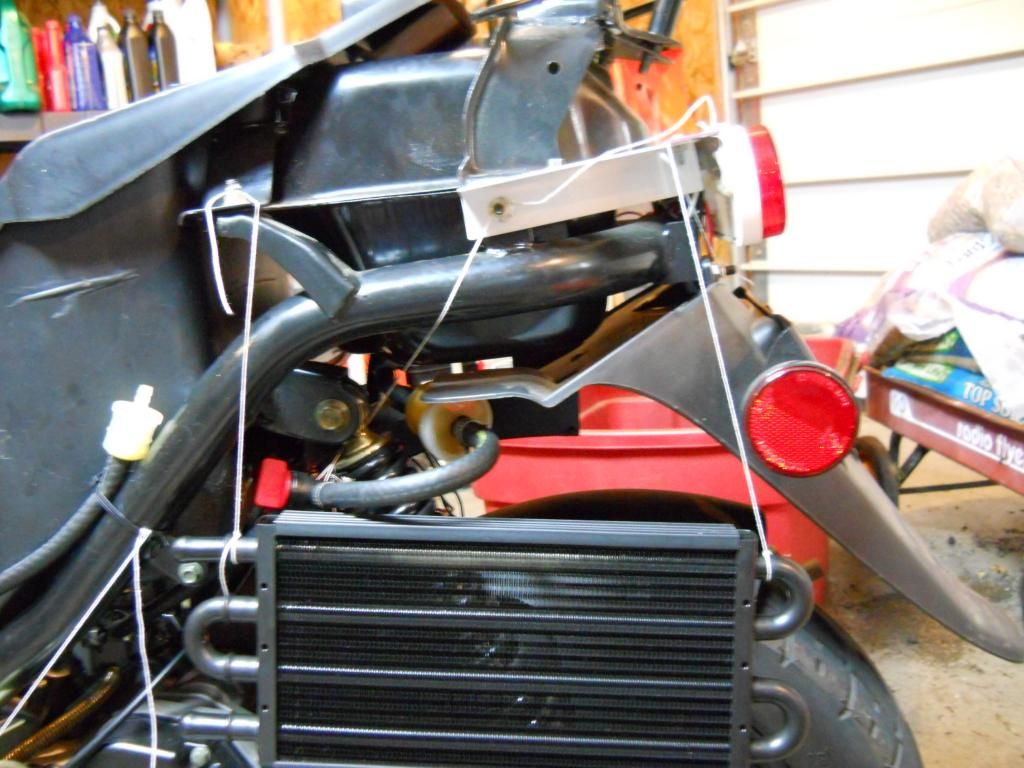 I think I will make something that will be held by the bolt you see in the upper-middle of the picture and go down to the top right of the radiator. Here is all the mounting hardware I have at hand, plus some scrap metal not shown: 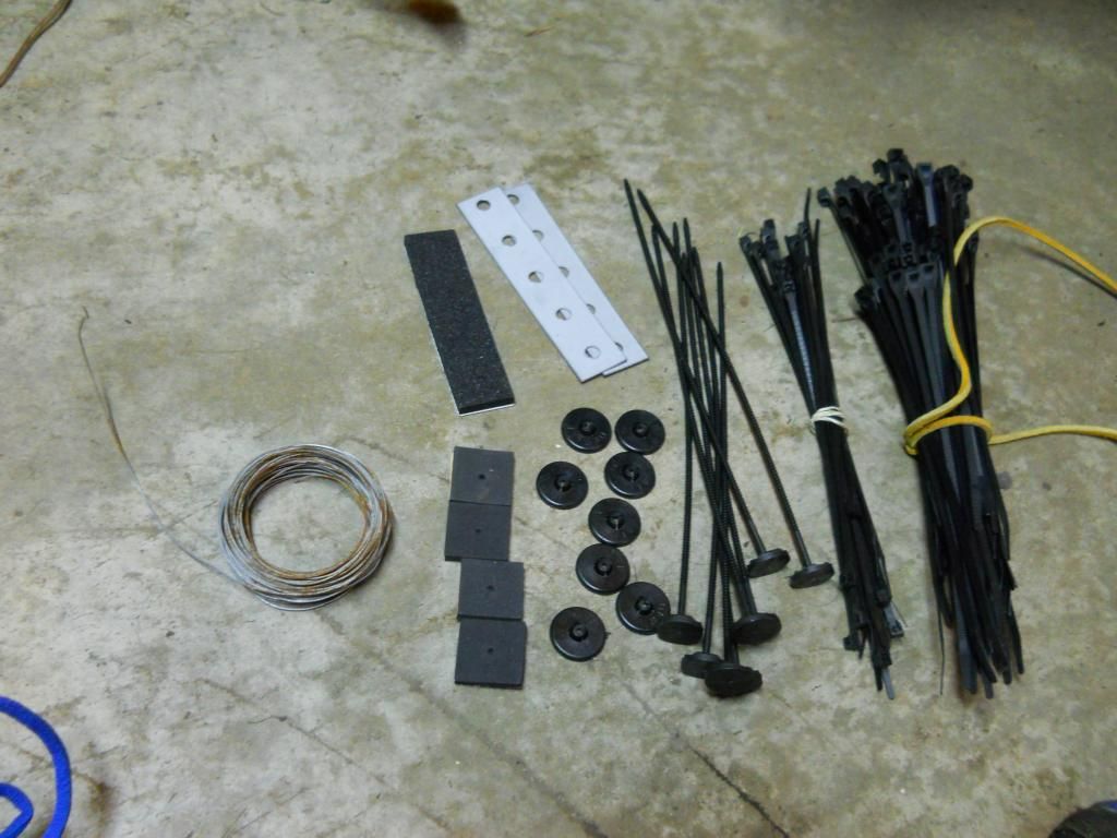 The metal wire is a last-ditch resort; I would rather use things like the metal strips. |
|
Doc's Anything Goes
Currently Offline
Posts: 371  Likes: 18
Joined: Jun 13, 2014 16:48:23 GMT -6
|
Post by glavey on Aug 8, 2014 9:11:59 GMT -6
Dang... I guess I was wrong. Since I already have the static balancer and the stick-on weights, I'll use those for now, but I'll definitely look at those in the future.
They seem to be just small 2-3mm metal balls, like BB's or buck shot. I wonder if I could use either of those instead?
Today I'll start mocking locations up for the pump, rad, and other items.
On a side note, I haven't had a headache in days! I don't know what I've been doing differently, perhaps it's the weather. Maybe I'm not so tolerant to heat as I thought I was.
Oh well, off to the garage!
|
|
Doc's Anything Goes
Currently Offline
Posts: 371  Likes: 18
Joined: Jun 13, 2014 16:48:23 GMT -6
|
Post by glavey on Aug 7, 2014 22:59:13 GMT -6
Honestly, I thought the beads were a bit gimmicky. Also, I'm pretty sure I have inner tubes.
|
|
Doc's Anything Goes
Currently Offline
Posts: 371  Likes: 18
Joined: Jun 13, 2014 16:48:23 GMT -6
|
Post by glavey on Aug 7, 2014 20:25:43 GMT -6
Well, I started off my making a few test washers to see what diameter hole will fit snugly on the 7.95mm machined rod I have; my printer as well as many FDM printers make undersized interior holes. It seemed that 8.2mm was too tight and 8.3mm was just a tiny bit loose so I went with 8.25mm. I modeled a 70mm tall cone with a 45mm base and cut a 8.25mm hole through the middle, and 3 hours later when it was done printing... the interior holes were too small! Such a waste of time and plastic, which I am running low on. I remade the cones with 8.35mm holes and only 30mm tall and 20mm dia. at the base. Those printed much faster and the holes were quite snug, but fit very well. I did manage to balance the front wheel to my liking, I could possibly cut one of my 7g weights in half and stick it too one spot, but I'll leave it as is seeing as how I only have 8 weights left, this wheel took 6, and I still have to do the rear wheel. One spot on the wheel opposite the valve stem needed about 37 grams. 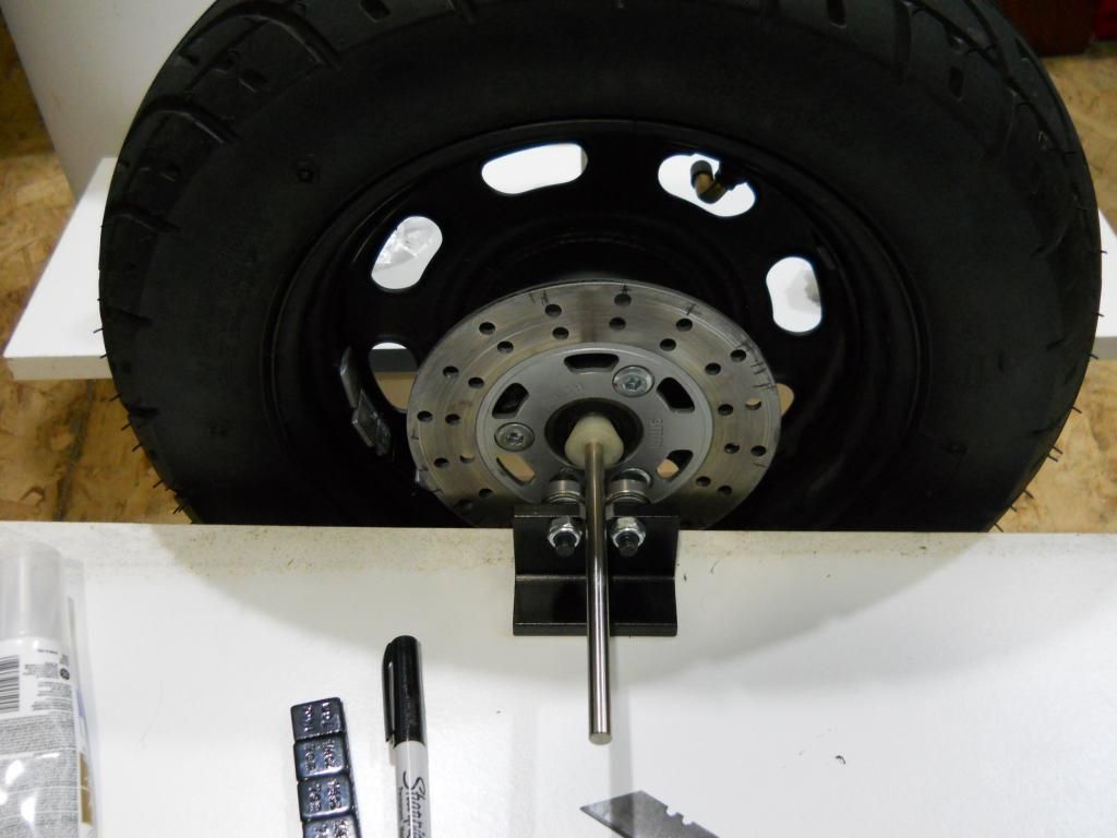 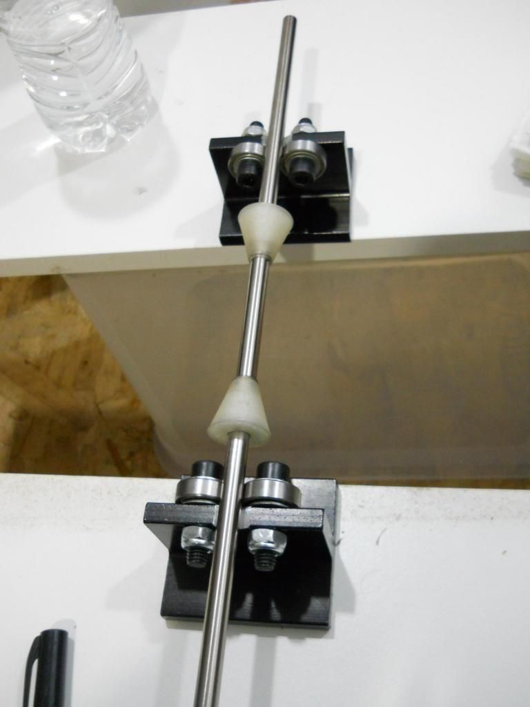 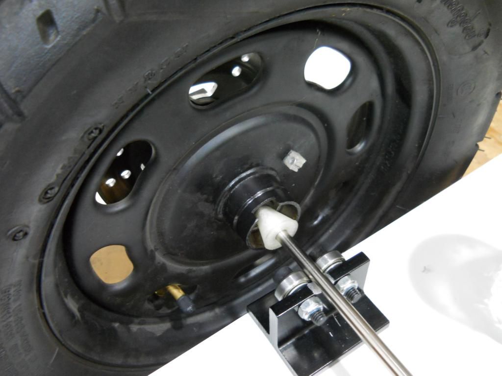 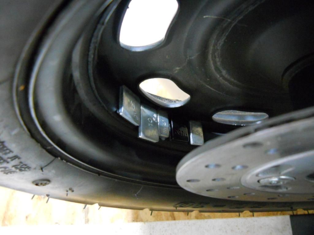 |
|
Doc's Anything Goes
Currently Offline
Posts: 371  Likes: 18
Joined: Jun 13, 2014 16:48:23 GMT -6
|
Post by glavey on Aug 7, 2014 9:40:07 GMT -6
Not too much has happened in the past few days as far as the scooter goes; I made my mother some lasagna, and have been helping her with her new laptop. Today, I installed the reed switch onto the speedo puck and glued a magnet to the front wheel. 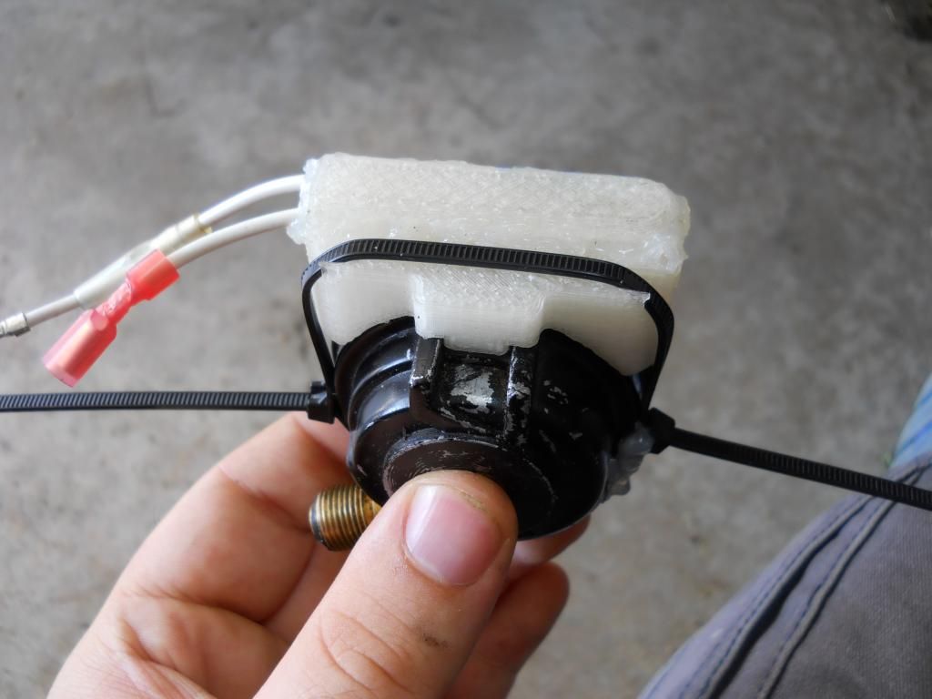 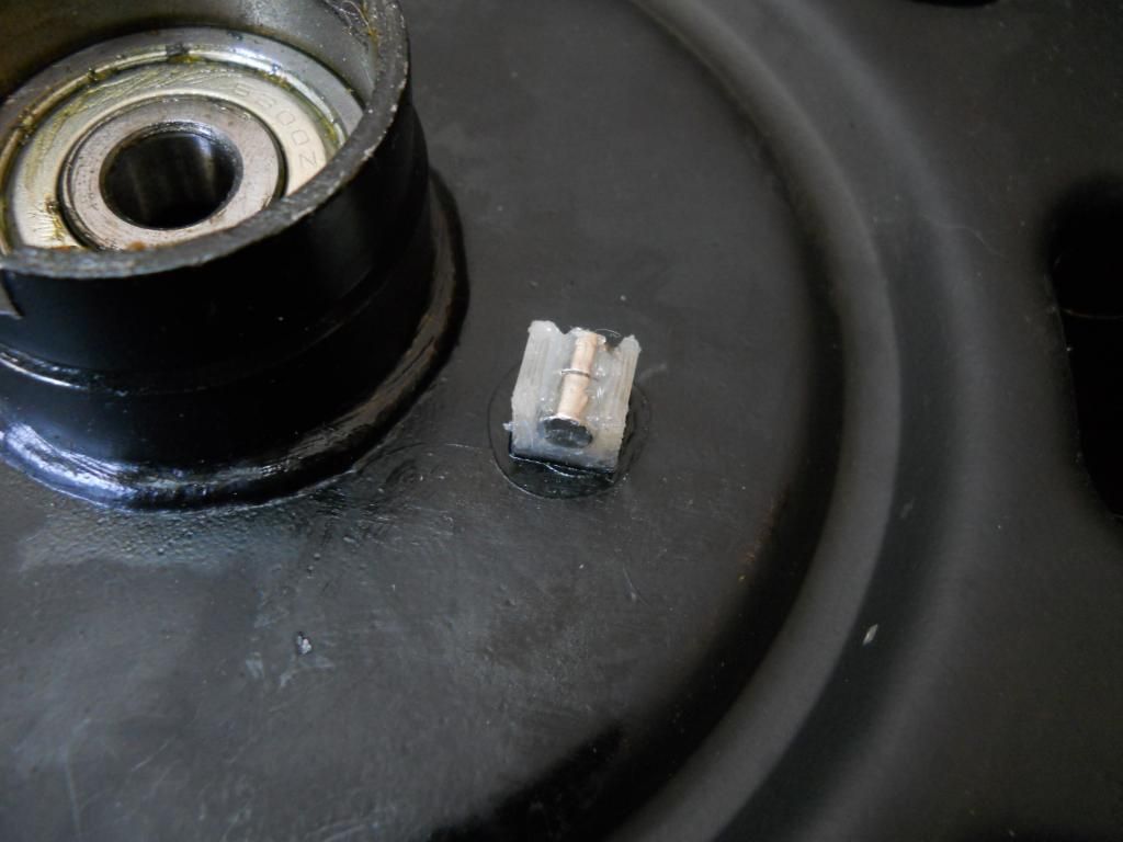 Now I'm going to (if I don't get distracted again and start daydreaming about cheese-injected sausages) model and make cones for the machined rod I am going to use for the wheel balancer and hopefully balance at least the front wheel. I SWEAR I am going to get to mounting the cooling loop soon. It seems like I am jumping around all over the place with micro-projects and not getting to the heart of why I made this thread in the first place. |
|
Doc's Anything Goes
Currently Offline
Posts: 371  Likes: 18
Joined: Jun 13, 2014 16:48:23 GMT -6
|
Post by glavey on Aug 6, 2014 13:34:57 GMT -6
Hmmm it appears that this welder has a gas hookup in the rear, as does this one from ebay. Yet again, the one from ebay looks chinese. However, it does appear that you can replace the entire MIG torch and hose/wire assembly. Here's a question I have about MIG welders; I know that some stick/arc welders are AC and some are DC, is this true for MIG welders too? |
|
Doc's Anything Goes
Currently Offline
Posts: 371  Likes: 18
Joined: Jun 13, 2014 16:48:23 GMT -6
|
Post by glavey on Aug 6, 2014 9:59:21 GMT -6
Oh man fleet farm... that name brings back memories. I used to live in a state that had those stores. I do have a tractor supply near by, they don't sell lincoln welders, but they do have this. Menards has this, sears has this and this, home depot has this, this, this, and this. So it seems if I want a "brand name" welder, I'm going to have to pay at least $50 more. My budget is about $170, perhaps a little more. The chinese welder might be repairable. Is it possible to retrofit a flux welder for use with gas or does it have to be designed for use with gas from the get-go? |
|
Doc's Anything Goes
Currently Offline
Posts: 371  Likes: 18
Joined: Jun 13, 2014 16:48:23 GMT -6
|
Post by glavey on Aug 6, 2014 9:32:23 GMT -6
Thanks bash, I'll look into those oil filters. Or perhaps one that doesn't cost more than the entire cooling project.
I designed this project to be as cheap as it can be. The parts for just the oil cooler assembly (not the arduino stuff), including all requisite hardware, fuel lines, fittings, pump, etc can be had for about $80. When I am completely finished I will post a complete BOM of all hardware being used in the system so anyone else who wants to do a similar project doesn't spend any money on something that they won't need or that won't work or break.
I have the pump connected via a toggle switch as well as a blade fuse. In theory, I could use the arduino to turn the pump on and off at a preset temperature.
For most people it is either love or hate for blue cheese, there seems to be no middle ground. When I was little my father used to take me to a store that sold nothing but wine and cheese and I guess that is where my addiction started.
|
|
Doc's Anything Goes
Currently Offline
Posts: 371  Likes: 18
Joined: Jun 13, 2014 16:48:23 GMT -6
|
Post by glavey on Aug 5, 2014 20:04:07 GMT -6
I've been toying with the idea to add some kind of filtration to this setup; I could hollow out an aluminum shell similar in shape to the check valve I have and add some very fine metal mesh - 100 microns or less, or I could use a filter intended for fuel that doesn't have any or too many plastic parts that would melt; perhaps something like those visu-filters that have brass elements in them. Let me see if I can find a pic of one...  I would avoid any that use plastic mesh or paper filters - I have a feeling those would either melt or clog and severely limit flow respectively. Yeah, I was testing the current draw of the pump to see how much if any headroom I will have with it installed and running. I think I can safely draw up to about 2.5 maybe 3 amps before charging voltage takes a dive. On a side note and a wee bit off topic; the pump consumes the same amount of power pumping oil as it does running dry. Just a stray tidbit of info I had. I would gladly model Cyborg's head but I am no good at modeling organic things, only mechanical parts. |
|
Doc's Anything Goes
Currently Offline
Posts: 371  Likes: 18
Joined: Jun 13, 2014 16:48:23 GMT -6
|
Post by glavey on Aug 5, 2014 16:33:01 GMT -6
I already have a tiny little 80 amp stick welder - for what it is worth. For $100 I could get a 250 amp stick welder on ebay, again I assume chinese made. What is the advantage or purpose of having DC current? The reason I am initially looking at mig welders is because most of the welding jobs I have to do are very small (as in the length of the weld, not the thickness of the material). Also, I'm not very good at striking an arc with the stick welder, but I guess that would come with experience and practice. I should also mention that I only have 120 volts available. I would like to weld with co2/argon but the cheapest mig welder that has support for gas is around $250-300; outside of my price range. The supported wire size of the 130 amp welder is .030" to .035"; widely and readily available. |
|
Doc's Anything Goes
Currently Offline
Posts: 371  Likes: 18
Joined: Jun 13, 2014 16:48:23 GMT -6
|
Post by glavey on Aug 5, 2014 12:18:06 GMT -6
Ok, thanks for the reply. Here is the welder I was looking at on ebay. |
|
Doc's Anything Goes
Currently Offline
Posts: 371  Likes: 18
Joined: Jun 13, 2014 16:48:23 GMT -6
|
Post by glavey on Aug 5, 2014 8:15:14 GMT -6
I just noticed that they have a small 90 amp flux core mig welder on sale for $90. I am a bit worried about something as dangerous as a welder being made in china, but the reviews on their site seem to say that it is pretty good.
I could also get a 130 amp flux core mig welder from ebay for $20 more, but it too is made in china.
Thoughts?
|
|
Doc's Anything Goes
Currently Offline
Posts: 371  Likes: 18
Joined: Jun 13, 2014 16:48:23 GMT -6
|
Post by glavey on Aug 5, 2014 8:03:25 GMT -6
I do have an exhaust gasket... kinda. The first time I took off the exhaust from the scoot I noticed the header flange wasn't flat at all. If you held a flat edge against one bolt hole, there would be about a 1/4 inch clearance between the other bolt hole and the flat edge. I reused the old metal and organic material gasket plus some high temp copper silicone sealant. I could try and bend the flange back to being close to straight, but I'm afraid I'll crack or break the welds joining the flange to the pipe. I do have a tiny little 80 amp stick welder, but have almost no experience welding, plus I'm pretty sure that 80 amps isn't enough for the thick flange. Yes, I am going to run the cooler with a pump. Thank you for the compliment on my cat. I do love her, even though she bites my nose in the morning and meows for hours in the middle of the night when she wants to be let inside. Yesterday I realized that the reed switch holder I made for my bicycle speedo wasn't going to work, so I designed and made a new one that will straddle the speedo puck and hopefully stay put. 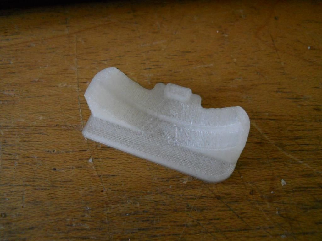 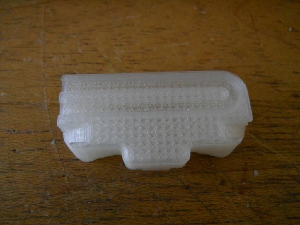 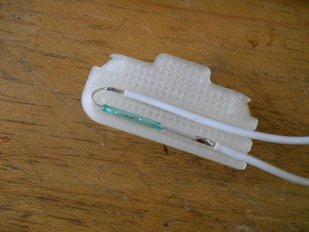 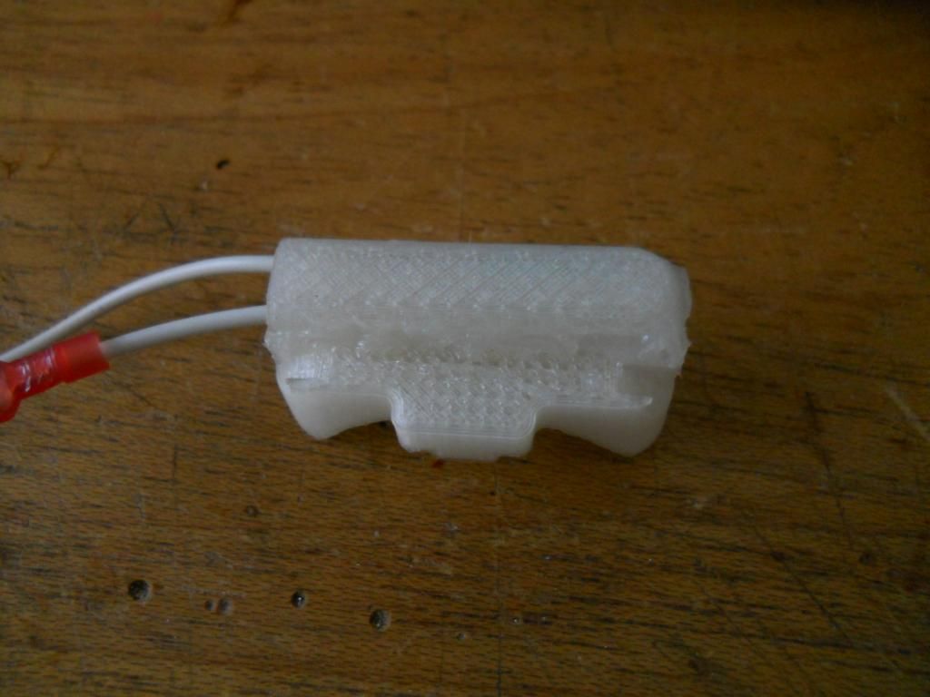 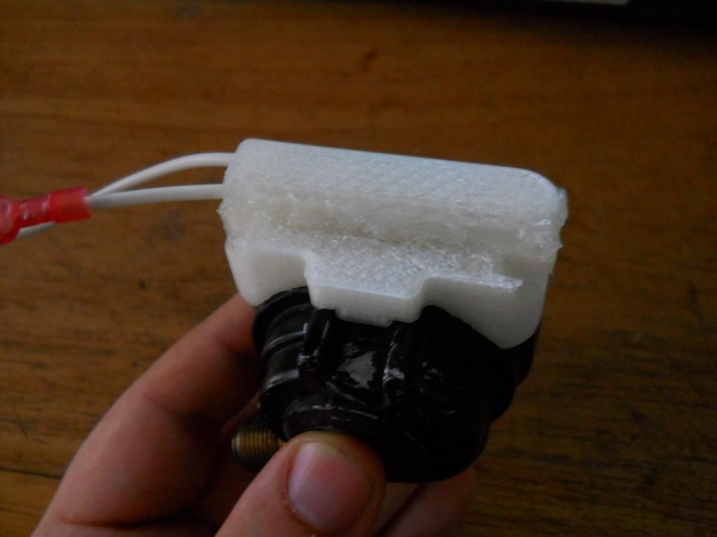 I tried to record some of the printing, but my camera's batteries died right after the first layer. I also noticed that my scooters wheels won't fit on the metal rod that came with the wheel balancer. I had some precision ground rods that I salvaged from taking apart printers lying around and found one that will work. The rod is MUCH smoother than the one that came with the balancer. I had to grind away a bit of material from between the bearings so the rod won't touch the bearing holders. 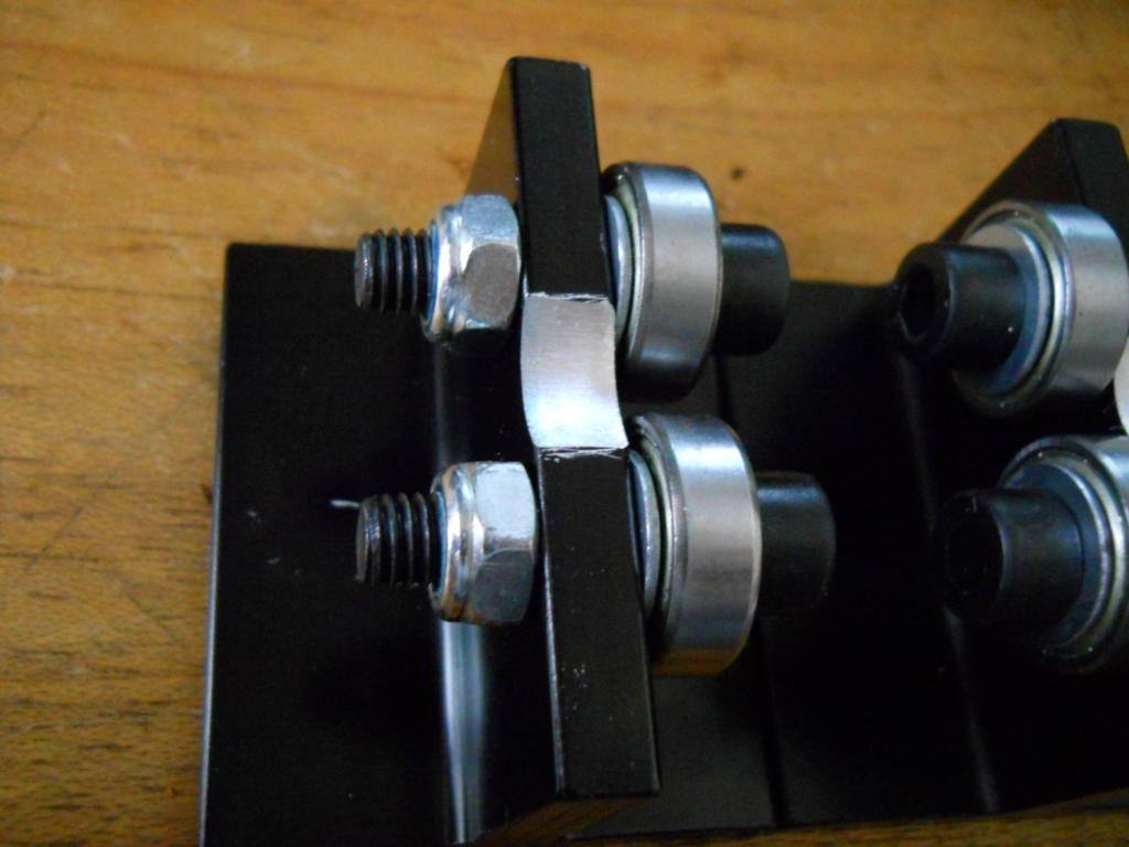 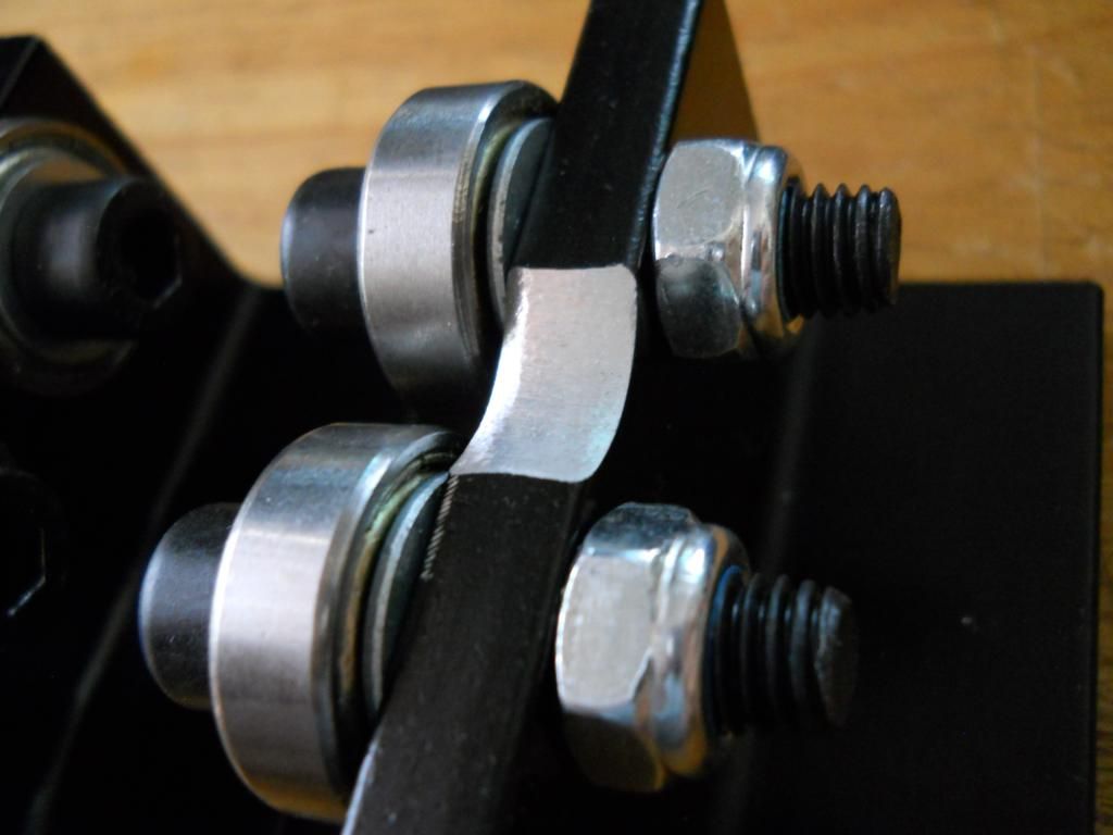 Now I just need to design and make some cones sized for that rod so I can balance my wheels. It did rain all last night and is still drizzling outside so no riding today, but I might try and figure out how I'm going to mount the radiator. Later dudes. |
|
Doc's Anything Goes
Currently Offline
Posts: 371  Likes: 18
Joined: Jun 13, 2014 16:48:23 GMT -6
|
Post by glavey on Aug 4, 2014 9:48:06 GMT -6
I rode my scoot to a doctor's office today. No mechanical maladies to report. I cruzed along at around 25 mph the entire way there and the oil temp only got to about 60c or 140f. Oddly enough when I got home I left the engine idling in the driveway so I could listen to it with my stethoscopes and the oil temp got up to 90c or 194f. I'm guessing the lower speed of the engine and thus the fan on the flywheel means less cooling. First I probed around the engine with the mechanic's stethoscope and found that the tick isn't incredibly clearly audible in any location that I probed, but it was at least noticeable in two places - the bolts that hold the intake manifold on and just above the oil filter drain, next to the oil fill and dipstick hole. Next I tried the real medical drum-type stethoscope. Man is this thing good! I can hold the drum a foot away from the cvt or engine and hear it clearly. I tested most of the same areas, although some I couldn't test because either I couldn't fit the drum in a tight space or I would have burned myself holding it there. The same places; intake manifold bolts and above the oil screen drain, I could hear the ticking sound. I recorded a video right after I was done probing the engine. You can hear the ticking best when the camera is pointing at the carburetor. Here is a video showing the fuel pump in action. I tested the amperage draw on the pump - it went between 0.3A to 2.1A, averaging about 1.6A. Yesterday I went to the local flea market and almost bought a timing light, dwell/tach meter, and a vacuum/compression/cylinder leakage gauge, but I thought I better save my money in case this ticking is something serious. |
|

