Doc's Anything Goes
Currently Offline
Posts: 371  Likes: 18
Joined: Jun 13, 2014 16:48:23 GMT -6
|
Post by glavey on Apr 26, 2015 11:57:28 GMT -6
Went for a short ride today and noticed a small problem. It seems that the cheap chinese voltmeter I bought doesn't like to work when I have the oil pump running. When I switch it off, it works perfectly. Oh well, it doesn't matter too much, I got the battery charging voltage dialed in when it was working, so now I can just use it to see what the battery voltage is before and after a ride. |
|
Doc's Anything Goes
Currently Offline
Posts: 371  Likes: 18
Joined: Jun 13, 2014 16:48:23 GMT -6
|
Post by glavey on Apr 28, 2015 17:09:48 GMT -6
|
|
|
|
Post by cyborg on Apr 28, 2015 18:56:38 GMT -6
Looks like new!!!!
|
|
Doc's Anything Goes
Currently Offline
Posts: 371  Likes: 18
Joined: Jun 13, 2014 16:48:23 GMT -6
|
Post by glavey on Apr 29, 2015 13:30:36 GMT -6
Just got back from the final ride around on the scoot while curing the paint. Nothing much to report, it was almost as if I was watching paint dry. Wait... I think I was watching paint dry. Anywho, here's the exhaust and muffler after being installed on the scoot and cured: 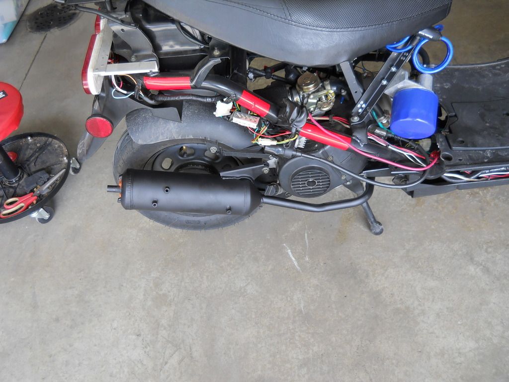 For those curious the curing process is (if piece is installed on vehicle): Run engine at idle for 10 minutes. Let engine cool for 20 minutes. Run engine at idle for 20 minutes. Let engine cool for 20 minutes. Run engine at normal operating temperature (go for a ride). Let enigne cool. Only time will tell if this paint will stay on and perhaps resist further rusting. |
|
|
|
Post by cyborg on Apr 29, 2015 14:05:17 GMT -6
Next time have it soda blasted then aluminized,,, then you can forget it,,, that stuff works real well
|
|
Doc's Anything Goes
Currently Offline
Posts: 371  Likes: 18
Joined: Jun 13, 2014 16:48:23 GMT -6
|
Post by glavey on May 27, 2015 8:45:42 GMT -6
As you may have deduced with my lack of updates compared to when I was working on the oil cooler, I am more mechanically minded than electronically minded. I've gotten into the electronics hobby only recently, but I've been building stuff as long as I can remember. Also, my ADD combined with multiple projects, and the fact that once I start a new project I quickly loose interest in anything I was working on previously, makes progress slow and often unnecessarily difficult. Here are a few of the things I've been working on, in addition to the tachometer: Remember that laser engraver I talked about briefly? The limited work area got to me very quickly. I took inspiration from this product, which uses the same electronics as the engraver I bought, but has a much bigger working area. All I had to buy was the pieces of the metal frame, $2.88/each for 5 pieces, 2x stepper motors for $5 each (got a huge deal there, they normally go for about $15 each, 2x pulleys (in retrospect, I could have made my own) $8 for two, though I forgot I would actually need 3 Doh! , 5' of gt2 belt $4, and another Kg roll of printer filament (I was going to make all of the frame pieces myself) $20. I won't go into the build process, but the end result, after about a week of designing and re-designing parts, is this: 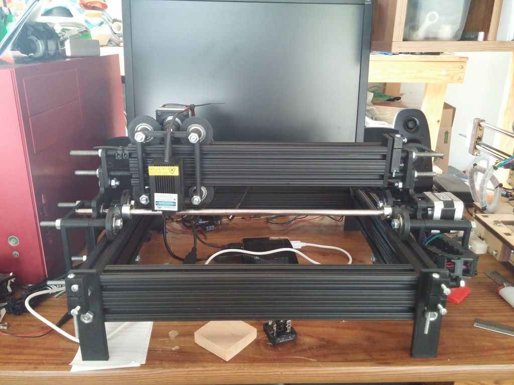 Now the (safe) print area is 200mm x 200mm; 5x more per axis than it was before. I have yet to get any software other than what came with the original engraver to work with it, but I'm pretty close. Next up is a very small project. As a soldering iron, I've been using one of those cheapo ones that plug directly into the wall, not regulated at all. My father used to make stained glass lamps and he used a dimmer switch to coarsely control the temperature of his soldering iron. I decided I would do the same. I salvaged an old computer power cord, connected it to a dimmer switch, and connected the dimmer switch to a dual outlet. I put the whole thing in a metal enclosure and printed a cover for the switches. Total cost: $2.05. I bought all of the electric parts minus the power cord from a local thrift store. I still need to buy/make a grommet so that the power cord going into the box isn't rubbing against sharp-edged metal. Here is the final product: 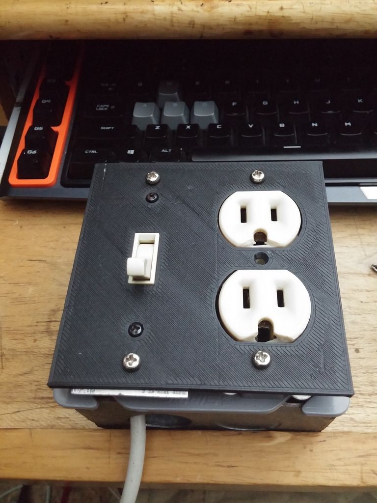 I tested it with the soldering iron I usually use, but that doesn't really make for good pictures as you can't see heat. Here it is with a lightbulb and an outlet adapter I keep next to the fuse box in case I have to determine which circuit a particular outlet or fixture is on: 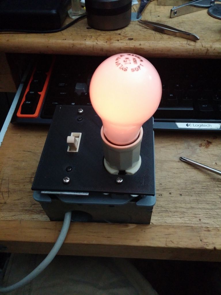 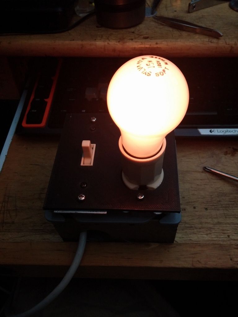 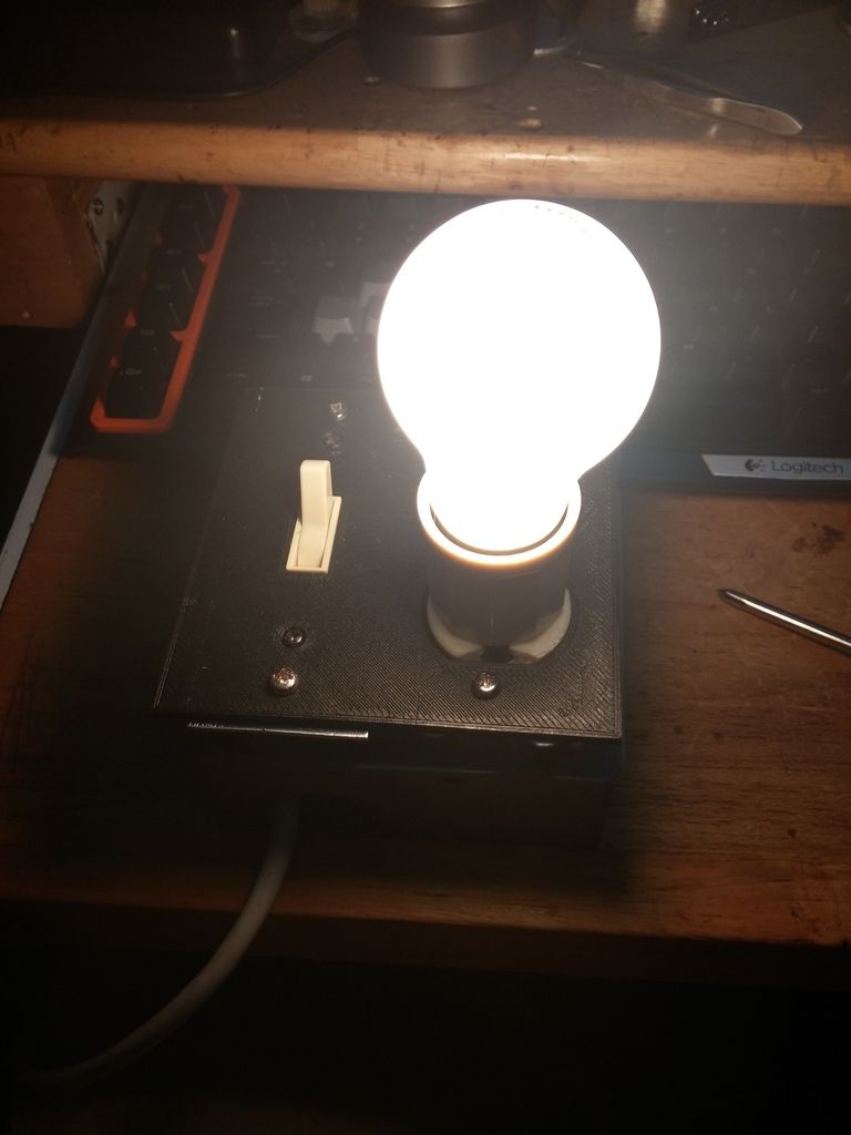 The third project I've been working on is using a solar charge controller to regulate the charging voltage going to the battery, instead of what I have now, which is a variable resistor I set to keep maximum voltage at around 14.3. The solar charge controller almost as a float mode charge controller - it reads the battery voltage and based on that is determines with how much voltage to charge the battery. The bulk of the charge is done at the usual 14.7 volts and once the battery is fully charges, it goes down to 13.5 volts to keep it topped off. It needs between 17 and 25 volts DC on the (solar array) input to charge the battery. I hooked up the charger to the scooter by taking the terminal from the regulator/rectifier that usually connects to the red wire and connecting it to the positive solar array terminal and connected the positive battery voltage to the red wire that usually comes from the regulator. Both grounds from the solar array and the battery were connected together and wired to chassis ground. Here's a few pictures showing the charger hooked up with two multimeters measuring the voltage coming out of the R/R before going into the charger (on the left) and the battery voltage, taken right at the battery (right). The engine wasn't running when I took these pictures, so the left meter is reading zero. The solar charger can display battery voltage or charging current. 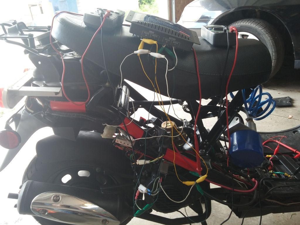 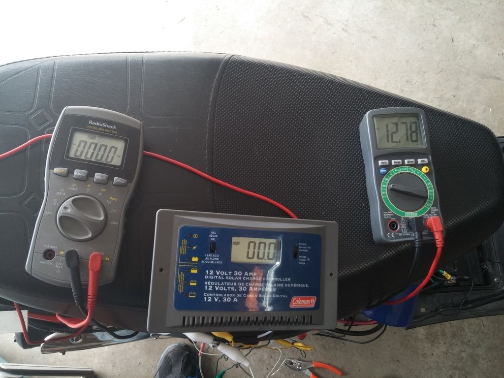 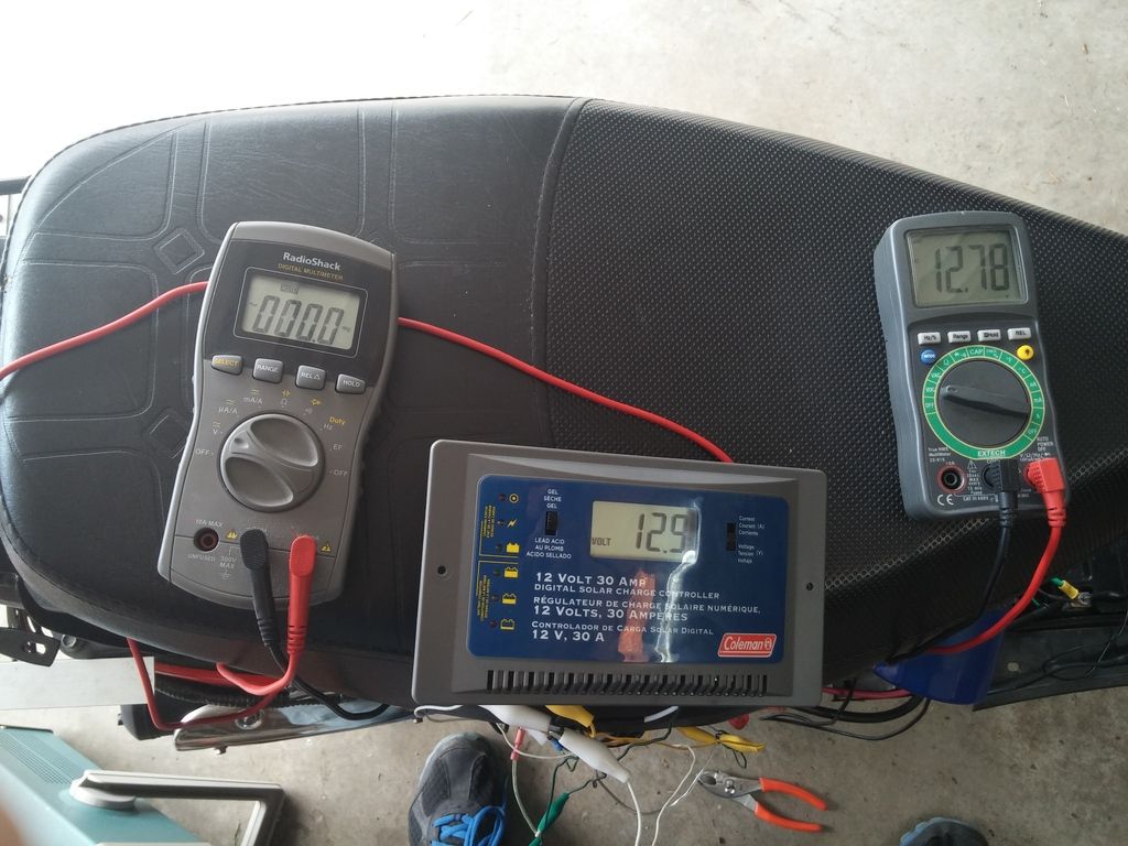 When I started the engine up the charger worked as it should. It took the voltage from the R/R, between 13 and 20 volts, and supplied the battery with up to 14.7 volts. I knew that the R/R for these scooters is only a half-wave rectifier, so I was curious how smooth or not smooth the power coming out of the R/R was. Here's a shot of my scope probing the terminal on the R/R that is usually connected to the red wire. This is with the solar charger still connected. Pretty darn messy. I wanted to see if adding another diode or perhaps a capacitor would smooth things out, but right before I got the chance to try either one of those, a quick torrential downpour of rain came across my neighborhood, so I had to wait a few minutes until the rain stopped and then a few hours to let the water that had come into the garage evaporate to go back and try again. The same darn thing happened again. Quick, violent downpour of rain that only lasted a few minutes. I decided I was done for that day. As you saw in one of the previous pictures, I had the solar charger tenuously connected to my scooter with very thin wires and alligator clips. Before I go out and test again, I need to make some more rigid connections and put the multimeters and the solar charger on a table so they don't vibrate off of the scooter. |
|
Doc's Anything Goes
Currently Offline
Posts: 371  Likes: 18
Joined: Jun 13, 2014 16:48:23 GMT -6
|
Post by glavey on May 28, 2015 19:40:14 GMT -6
Little bit of progress with the solar charger today. I got it wired up with more substantial wires and held in position temporarily with galvanized wire. 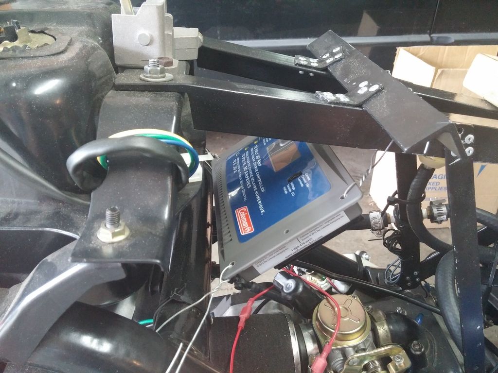 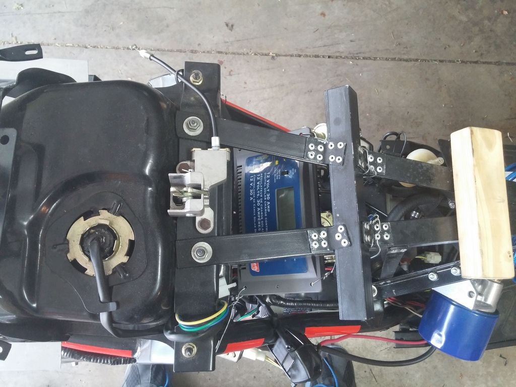 I tested the charger with the engine running from idle up to about 5-6k rpms. The battery voltage peaked at 14.7 volts when the charger was in its bulk charging mode and went as low as 13.8 volts during its float mode/topping off mode. The voltage coming out of the R/R stayed between 13 and 19 volts. The most amperage I saw the battery take was 0.3 amps (without the fuel/oil pump running). That might be because the battery was very near fully charged when I had the engine running. The solar charger can take up to 30 amps, so I have no worries that it will blow from over-current. I still have yet to remove the variable resistor that I was using before to control the charging voltage, but I have it set so that there is almost no voltage drop caused by it so I can still use the scooter until I remove it. One mistake I made today was thinking that a 30 volt, 3 amp rated circuit can take 36 volts and 2.2 amps. 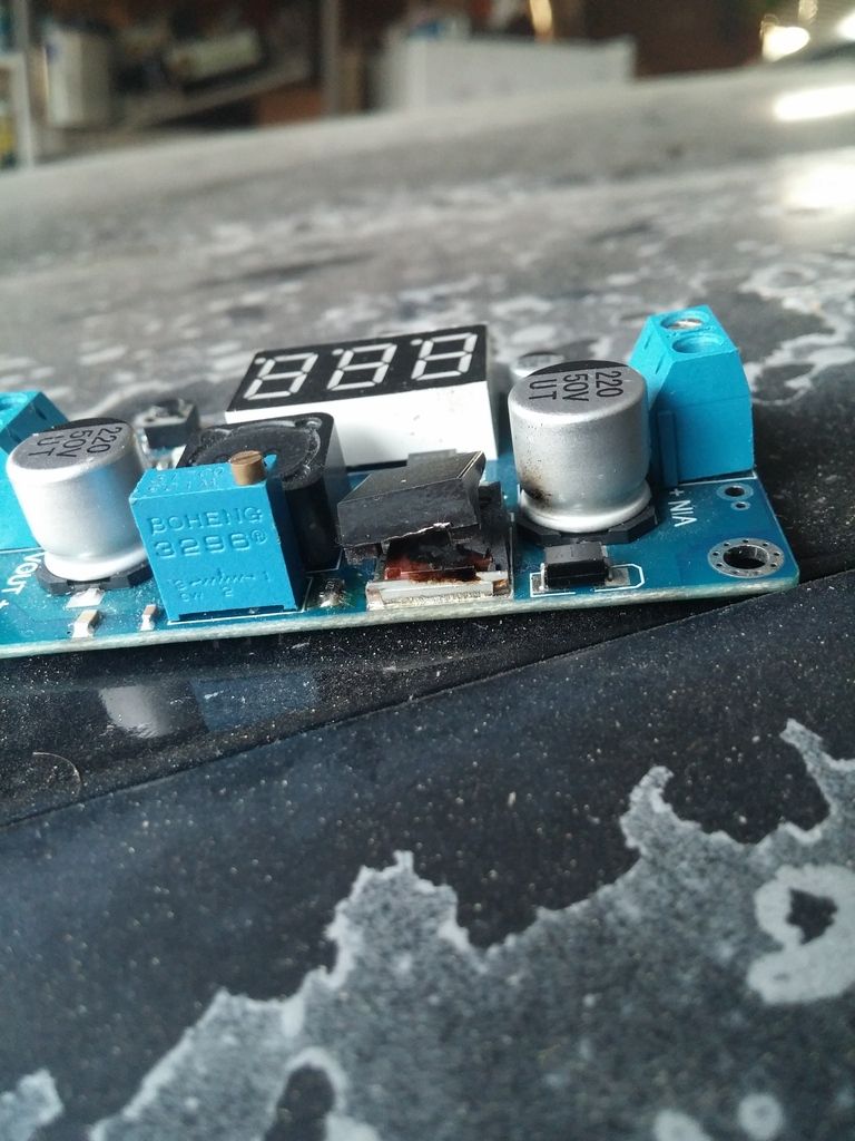 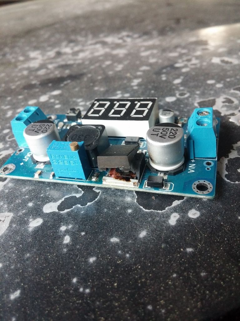 I didn't get hurt, just the one IC was blown, and the whole module was just a piece I use to test circuits with my arduino, so I haven't lost a whole lot. |
|
|
|
Post by cyborg on May 28, 2015 21:44:49 GMT -6
Please tell me that's not the paint on the hood of your car,,,, lie to me,, anything I'll believe you
|
|
Doc's Anything Goes
Currently Offline
Posts: 371  Likes: 18
Joined: Jun 13, 2014 16:48:23 GMT -6
|
Post by glavey on May 29, 2015 3:11:47 GMT -6
Ok, I'll lie to you, but I'd be lying to you.
Many cars of my model year have the same problem; there was something like a defective top/clear coat on those specific cars.
|
|
Ad Free Donut
   
Currently Offline
A bike is music to my ears.
Posts: 1,655
Likes: 93
Joined: Oct 22, 2013 4:11:04 GMT -6
|
Post by Guitarman on May 29, 2015 3:35:00 GMT -6
MOST cars from before 2004 or 05 have that same problem here in Hawaii. The UV here is intense and a bad UV coat will leave your car looking like that.
|
|
Clinician

Currently Offline
Posts: 12
Likes: 2
Joined: May 29, 2019 17:42:16 GMT -6
|
Post by ricktheslickster on May 29, 2019 20:25:37 GMT -6
I
|
|
Clinician

Currently Offline
Posts: 12
Likes: 2
Joined: May 29, 2019 17:42:16 GMT -6
|
Post by ricktheslickster on May 29, 2019 20:31:52 GMT -6
No, your cat is trying to tell you something...She's saying, "Look at me! I'm a giant radiator slapped to the side a tiny moped!"
|
|

