Certified Clinician

Currently Offline
Posts: 81
Likes: 0
Joined: Mar 16, 2011 12:32:15 GMT -6
|
Post by philosophydoc on Jun 17, 2011 15:13:23 GMT -6
No -- no brake lights.
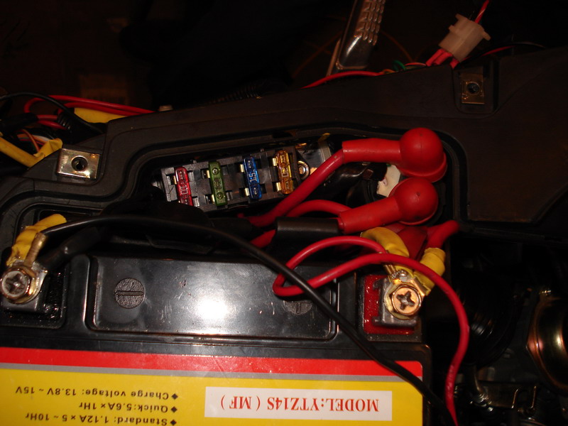
A correction -- where the main harness splits, there are five bundles; the three that are connected to go to the radiator fan, the coil, and the thermo switch at the base of the radiator.
Found an earlier post in another thread by JR where he says:
So the black/white and green are a kill switch...that connect to what? I have read of some scoots with a kill switch connected to the side stand, making it impossible to start the scoot with the stand down, but there is no connection there I can see. I do have a black/white going to the CDI.
|
|
|
|
Post by Cruiser on Jun 17, 2011 18:21:31 GMT -6
The black/white wire also runs to the ignition switch and the kill switch. The green wire is a ground which attaches to the frame of the scoot which is in turn attached to the ground or negative cable of the battery.
A multimeter is a good tool for checking things out here. I would disconnect the negative of the scoot's battery before doing any checks. Set the meter on the lowest resistance (R X 1). Attach one lead to ground (a clean metal spot on the engine) and the other lead to the black/white wire on the CDI connector and the mystery molex. They both should read zero or within 1 or 2 ohms. Ohms are a unit of resistance. These measurements are taken with the ignition in the off position. Turning the ignition on should give a maximum reading which is the same as you would get by removing one of the test leads from the circuit being tested. You also should be reading close to zero when checking the green wire on the mystery molex.
The brake light circuit has to be functional in order for the starter to work. It isn't necessary to have actual brake lights attached, but the brake switch on at least one of the brakes has to be working. Working brake lights will tell you that the brake switch(s) is OK. The brake circuit supplies 12 volts to one side of the starter relay. The starter button completes the circuit by supplying the ground to the other side of the starter relay. Most 250cc scoots use a yellow/green wire for the brake circuit feed to the starter relay and a red/yellow wire for the starter button feed.
Set the multimeter to read volts DC (the 20 volt range is good). Better meters are auto ranging. Connect the black lead to a good ground. Reconnect the scoot battery negative lead. Turn the ignition key on and use the red meter lead to see if you get 12 volts on the starter relay at the yellow/green when you press either brake. You should also have 12 volts on the red/yellow at this time as it is feeding through the starter relay coil. Pressing the starter button should make the red/yellow wire go to zero volts.
A quick check of the starter can be done by momentarily bridging the two big terminals on the starter relay with a screw driver.
So, you have some homework to do. Let us know what you come up with after doing your meter checks.
|
|
Certified Clinician
Currently Offline
Posts: 81
Likes: 0
Joined: Mar 16, 2011 12:32:15 GMT -6
|
Post by philosophydoc on Jun 17, 2011 20:00:34 GMT -6
Okay! (Multimeter is Innova 3320, auto-ranging)
Yes, this scoot a yellow/green wire connecting to one side of the starter relay, and a red/yellow wire coming from the starter button.
Here are my readings:
(1) The B/W wire at both the mystery molex and the CDI connector read .4 (four-tenths) ohms
(2) The green wire at the mystery molex reads .2 (two-tenths) ohms.
(3) Set multimeter to DC, reconnected battery, clamped left brake lever, turned ignition key on, checked yellow/green at starter relay -- 0 volts. Tried again with right brake lever, same result.
(4) A quick bridging of the relay terminals caused the starter to engage...(but I only bridged it for a second).
Hence the brake circuit seems the likely culprit...what should I do next?
(Many, many thanks...)
|
|
|
|
Post by Cruiser on Jun 17, 2011 21:16:22 GMT -6
Many scoots have a fuse for the brake lights. That is good place to start. Should be able to measure 12 volts on either side of the fuse with the ignition on. This 12 volts is fed directly from the ignition switch usually through a black wire. Either a black or white/red wire then goes from the fuse to both brake switches.
|
|
Certified Clinician
Currently Offline
Posts: 81
Likes: 0
Joined: Mar 16, 2011 12:32:15 GMT -6
|
Post by philosophydoc on Jun 17, 2011 23:49:46 GMT -6
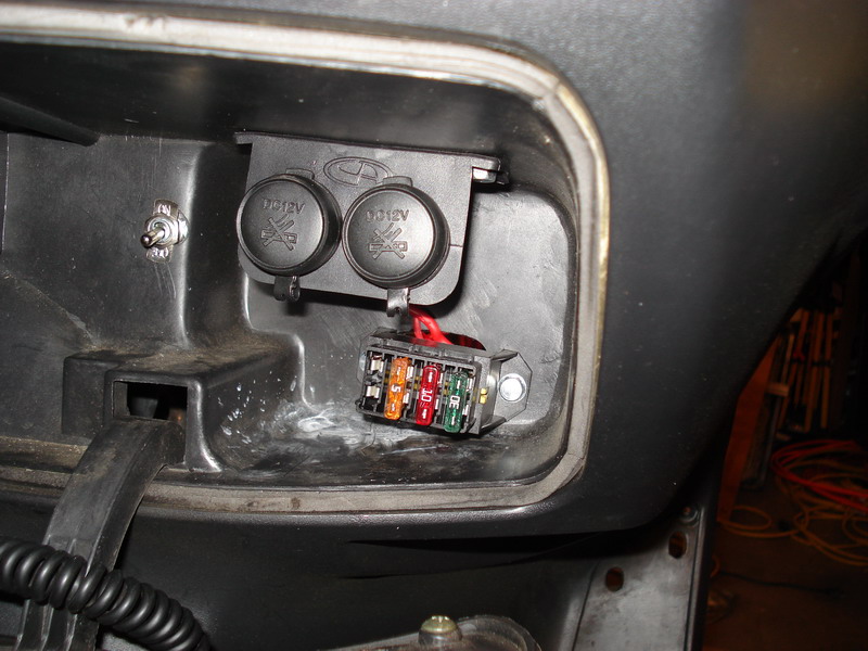
Okay, bear with me on this...don't know much about how electrics work on a bike. I cannot find any more fuses on the bike (outside of the fuse from the starter to the battery). I have a fuse box that was in the box of parts that came with the bike, a fuse box with 4 fuses (8 wires) that terminates in a six pin molex connector, a connector whose mate is NOT anywhere on the bike. Now I also have six cut wires, but the colors of the six wires do not match colors of the six wires on the molex connector. Here is a drawing of the fuse box, using the fuse labels from the inside cover of the fuse box, and the wire colors coming out either side of them: 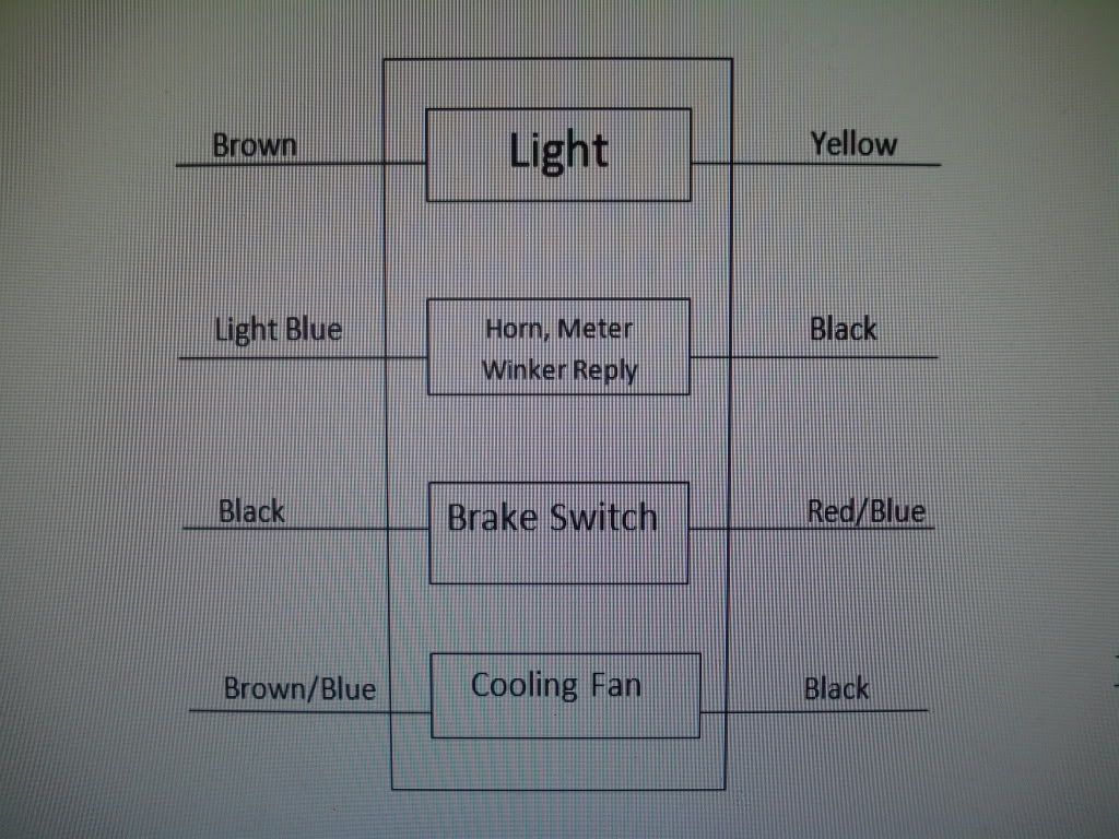 As you can see, there is a "brake switch" fuse here, with a black and red/blue wire coming off either side of the fuse. It is also the case that one of my cut wires is black, and in your last message you noted that a black wire should go to the brake fuse. If I crimp a blade connector on my cut black wire and connect it to the corresponding black wire on the molex connector, current will flow through the black wire, across the fuse, out the red/blue wire, and then have nowhere to go...? I don't even know if the cut black wire is carrying any electricity...how can I set up the multimeter to check this, or is this not the correct way to proceed? Here is the six pin molex connector at the other end of the fuse box : 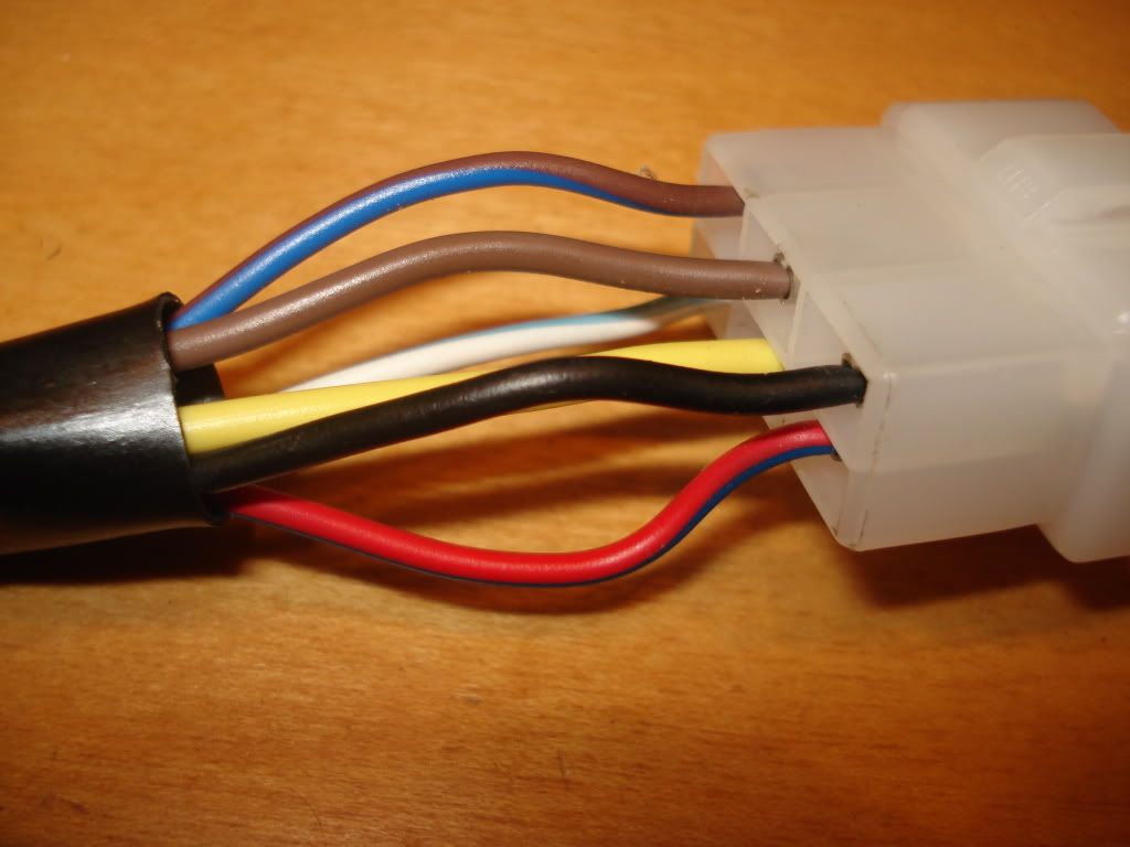 Thanks again... |
|
|
|
Post by Cruiser on Jun 18, 2011 11:31:17 GMT -6
My scoot has that fuse box located down by the battery. You noted earlier that some cut wires near the instrument panel included black and blue/red. Strip a little of the insulation off the ends of these wires so you can make some measurements. Check the black for 12 volts when the key is turned on. Check the blue/red for voltage also. If the blue/red has no voltage, then set the meter for resistance measurement and squeeze either brake handle. If the resistance goes from max to a low value (not zero) then you have found the feed wire for the brake lights and are measuring the resistance of the brake light bulbs. If the brake lights are not connected, then the resistance reading will not change or the blue/red has nothing to do with the brakes. So, it's a good idea to make sure you have the brake bulbs and wiring connected for them.
If this works out to be the brake light circuit, then you can put a 10 amp in-line fuse across the black and blue/red. It looks like a piece of the wiring harness is missing or certainly a molex connector and you will have to piece meal each circuit as you identify it.
|
|
Certified Clinician
Currently Offline
Posts: 81
Likes: 0
Joined: Mar 16, 2011 12:32:15 GMT -6
|
Post by philosophydoc on Jun 20, 2011 16:20:23 GMT -6
I checked the cut black wire, and it reads 12.73 volts (same reading I get from the battery).
No voltage from blue/red. Checked blue/red for resistance – reads upper 20s, with no change when squeezing brake handles.
I have removed the front cowling, and the cover in back of handlebars to expose wiring. From each brake lever, two wires emerge – one yellow/green and one black.
The two yellow greens merge into one yellow/green. The rear brakelights both have yellow/green wires running to them. (I still cannot get any of the rear lights to work.) Using the multimeter, I tested the yellow/green wire for continuity throughout the bike – from where the two y/g wires merge together behind the speedometer all the way to the two taillight bulbs, and the wire appears fine (it beeps loud and clear).
Now the two blacks coming out of the brake levers merge and become one red\green. Since one of my cut wires is a red/green wire, I tested it for voltage – only reads 5 millivolts. I also tested for resistance – reads around 35, with no change when brake handles are squeezed.
What does this tell you?
|
|
|
|
Post by Cruiser on Jun 20, 2011 18:31:07 GMT -6
It sounds like the circuit from the switch to taillights is good. Did you check it to the starter relay? If that's OK, then I would check for continuity between the cut red/green and the red/green on the brake switch circuit. Does the cut black wire work with the ignition switch? If the red/green has continuity and the black works with the ignition switch, then I would put a 10 amp inline fuse between the black and red/green wire. That should light the brake lights and feed 12 volts to the starter relay.
|
|
Certified Clinician
Currently Offline
Posts: 81
Likes: 0
Joined: Mar 16, 2011 12:32:15 GMT -6
|
Post by philosophydoc on Jun 20, 2011 19:43:58 GMT -6
Yee-Hah! Yes to everything...
Yes, there is continuity between where the yellow/green wires merge behind the instrument panel and the starter relay.
Yes, there is continuity between where the two black wires merge (coming out of the brake levers) and the cut red/green wire.
Yes, the cut black wire works with the ignition switch (0.00 when off, 12.73 volts when turned on).
I will pick up the inline fuse tomorrow.
I gather your advice is to simply place a series of inline fuse between wires as it becomes clear which wires should be connected, rather than trying to create a new fuse block (or re-use the old one)? If so, any particular reason why?
Thanks again for you time and wisdom.
|
|
Scooter Doc

Currently Offline
Vstar 650 Classic
Posts: 675
Likes: 3
Joined: Apr 24, 2010 19:43:21 GMT -6
|
Post by damin69 on Jun 20, 2011 20:25:59 GMT -6
|
|
|
|
Post by Cruiser on Jun 20, 2011 22:06:07 GMT -6
Yee-Hah! Yes to everything... Yes, there is continuity between where the yellow/green wires merge behind the instrument panel and the starter relay. Yes, there is continuity between where the two black wires merge (coming out of the brake levers) and the cut red/green wire. Yes, the cut black wire works with the ignition switch (0.00 when off, 12.73 volts when turned on). I will pick up the inline fuse tomorrow. I gather your advice is to simply place a series of inline fuse between wires as it becomes clear which wires should be connected, rather than trying to create a new fuse block (or re-use the old one)? If so, any particular reason why? Thanks again for you time and wisdom. Your welcome. The fuse can be placed physically anywhere you want on the scoot. Just make sure that it is between these two wires. You will have to run extra wiring to place the fuse in another location. A central fuse block may be a little more involved for all the circuits once you determine how to wire it up, but it will make it a lot easier to change fuses and also determine when and if a fuse blows. The fuse block pictured by Todd is superior to the OEM in every way. |
|
Certified Clinician
Currently Offline
Posts: 81
Likes: 0
Joined: Mar 16, 2011 12:32:15 GMT -6
|
Post by philosophydoc on Jun 22, 2011 0:51:11 GMT -6
I decided to pick up a fuse block and will mount it next to the battery. A few more items to report... The two wires that connect to the radiator fan are pink and orange/white; the two wires that connect to the thermoswitch at the base of the radiator are green and orange/white. There is continuity between the cut pink wire and the pink wire at the fan. There is also continuity between the orange/white wire at the fan and the thermoswitch. This suggests the following. Look at the wiring diagram below, which I am finding is very close to mine:  There is a wire that runs from the right side of the thermoswitch to the right side of the fan whose color is not identified (though the 250T Jonway diagram found here i905.photobucket.com/albums/ac258/bashan_2010/DIAGRAMS/Jonway_250T-2-1.jpg has the wire as pink. Now I have a pink wire, but mine does run between my fan and thermoswitch. I believe on my scoot, the orange/white wire is the wire that connects the thermoswitch and the fan (again, because I have continuity between where the O/W connects at the fan and at the thermoswitch. And there is NO continuity between the cut pink and the O/W wire.) If so, then (going back to the wiring diagram above) there should be a fuse on other wire coming out of the thermoswitch (a green wire in my case). Is that correct? I have checked the Lance Duke wiring diagram, and while the wire colors are different, it also shows one wire running between the fan and the thermoswitch, and a second wire running from the thermoswitch that is also fused. (On the Lance diagram, it is fused at the fusebox at the top of the page). Here's my problem -- if I connect my fuse box to the cut pink wire (so the fuse has a pink in one side, and a black on the other), I'll have a fuse on the fan, but not the thermoswitch. Would that be okay instead? I can see no way to fuse the green wire, short of cutting into it. Also, the cut blue/red wire goes the the emergency flasher. On the Lance diagram, the flasher has a white/red, green and gray, and the white/red runs to the fuse box. On my bike, the flasher has blue/red, green, and gray. Again, using the Lance diagram, that suggests I connect a third fuse as follows -- blue/red on one side of the fuse, black on the other. I imagine this connects to what the fusebox calls the "Horn, Meter, Winker reply"? I am still puzzled by the two yellows -- I have a plethora of yellow wires coming from the instrument panel, most of which seem to come from dash lights (at least four lights have yellow and green wires coming out the back). Thanks again... |
|
|
|
Post by Cruiser on Jun 22, 2011 11:44:27 GMT -6
A very quick reply. No fuse is used on green wires. They are usually ground wires and only the hot or feed wires are fused.
|
|
|
|
Post by Cruiser on Jun 22, 2011 12:28:21 GMT -6
I'm looking at the cooling fan circuit here. The circuit path looks like black wire (12V) through fuse that you supply (10 A) through pink wire to fan through orange/white to thermo switch and then to ground through the green wire. The green wire should already be feeding to ground.
Digest this and I will try digesting the rest of your post when I have a little more time.
|
|
Certified Clinician
Currently Offline
Posts: 81
Likes: 0
Joined: Mar 16, 2011 12:32:15 GMT -6
|
Post by philosophydoc on Jun 22, 2011 13:34:35 GMT -6
Okay, I think I have the fuse box figured out... In a previous version of the following diagram, I listed the fuse box with the wire colors coming off the box. I have changed the diagram here, and am using the cut wire colors to show how I think the cut wires should connect to the fuse box: 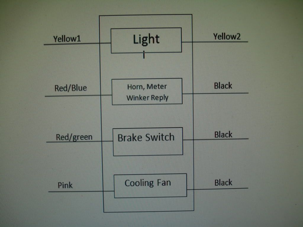 Fuse 1 Yellow1 -- continuity to the instrument panel Yellow2 -- continuity to the red wire on Rectifier/Regulator. R/R has three yellows, and red, green, and black wires. The red, green,and black connect to a molex on my scoot, at which point the red changes to my Yellow2. On the Jonway wiring diagram posted earlier, a 10 amp fuse does appear on the red wire, and the other end of that wire runs to the "meter light" on instrument panel, so I feel pretty good about this fuse. Fuse 2 Red/blue -- continuity to Emergency flasher Black As noted earlier, Lance diagram has White/Red here that is fused. Again, this seems correct. (Only problem is that my horn was working without this fuse...) Fuse 3 Red/green -- continuity to starter relay Black This should allow the scoot, when switched on, to get juice across the starter relay. Fuse 4 Pink -- continuity from cut wire to radiator fan Black This is the one I am most unsure about, as I can't find any wiring diagram that shows a fuse to the fan, but only to the thermoswitch. I started peeling back some sheathing, and it turns out the cut pink wire is simply the opposite end of the pink wire coming from the fan; moreover, the other wire to the fan (orange/white) only runs from the fan to the thermoswitch. Hence all the remains (to provide power to either the fan or the thermoswitch) is the green wire at the thermoswitch...could that provide power? Since I tend to associate green with ground, it seems the pink wire needs juice, and connecting it via the fuse to the black wire (which gets juice when the ignition is turned on) would provide that. Does this seem correct? Any obvious errors? I am ALMOST feeling confident.... |
|