|
|
Post by Cruiser on Jun 22, 2011 17:33:00 GMT -6
Did you read my post just before yours? That explains the cooling fan connections. Your scoot's convention is opposite that of the wiring diagrams that we have on the forum. The thermo switch is on the ground side instead of the power side of the fan. So your fuse 4 should be OK.
Fuse 1 - does your scoot have a blocking diode? If there is no headlight on/off switch, then you must have a blocking diode which means that the setup you describe should work.
Fuse 2 - sounds like it could work. However, if you had no fuses before, how did the horn work? Maybe through the main fuse that you described earlier as being on the starter relay?
Fuse 3 - the starter relay should have no direct connection to a ground or 12 volts. Most scoots use the start button to supply a ground connection and either brake switch to supply the 12 volts. The 12 volts for the starter relay has to come from the brake switches. What are the colors of the small wires that go to the starter relay?
Fuse 4 - OK. See above.
|
|
Certified Clinician

Currently Offline
Posts: 81
Likes: 0
Joined: Mar 16, 2011 12:32:15 GMT -6
|
Post by philosophydoc on Jun 22, 2011 19:41:59 GMT -6
Okay, wired it all up and tried to start it. First, lights came on, turn signals worked, but no brake lights (or at least no additional lights came on when I squeezed either brake handle). Bike turned over but never caught...but then I saw coolant leaking and stopped to locate problem. Hard to see here, but here's a photo of where it seemed to leak (this is about 3 hours after I stopped cranking...) 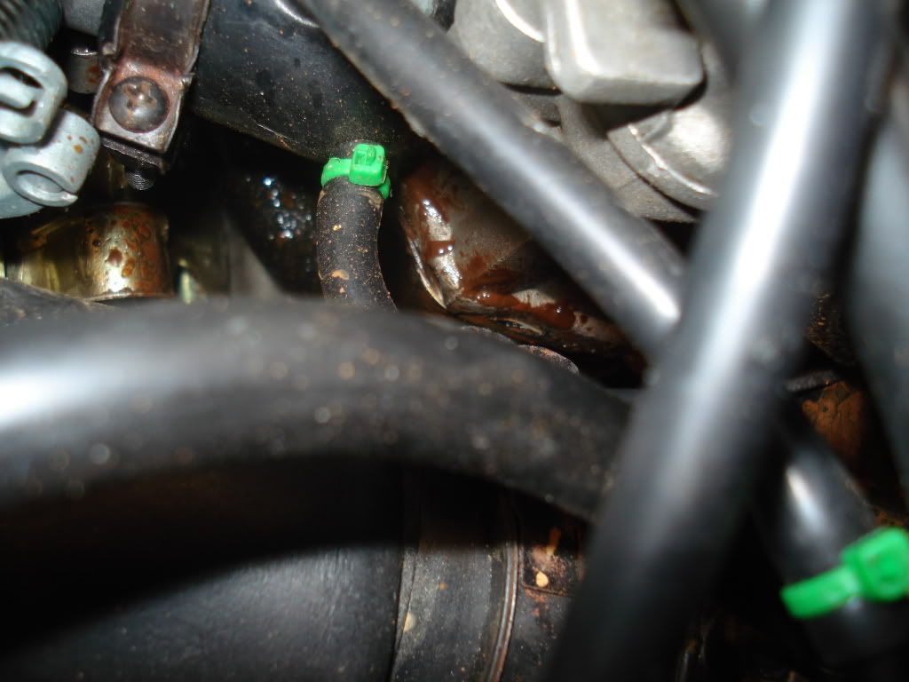 Is the reddish-brown liquid what coolant looks like when it dries? It's Prestone 50/50; I completely flushed the system and added it about on week ago. Also -- ugh -- the leaking appears to be from the head gasket. Would a bad head gasket cause a coolant leak, or should I be looking elsewhere? Look closely at where the cylinder head and cylinder meet -- should they . Also, looking along that edge, you can see where the gasket is pulling away...again, would a bad gasket here cause coolant to leak? Cruiser, in response to your questions, yes I have a blocking diode. And the wire colors to the starter relay are red/yellow and green. Of the four fuses in the original fuse box, on three of them one side was black. I've replicated that as well, so the pink, red/green, and blue/red all pair with a black wire, and all the blacks are soldered together about 6 inches after leaving the fuse box. The final fuse has the two yellow wires, one of which leads back to the R/R. |
|
Certified Clinician
Currently Offline
Posts: 77
Likes: 1
Joined: Nov 2, 2010 17:18:26 GMT -6
|
Post by Jeff on Jun 22, 2011 20:54:11 GMT -6
Usually a blown head gasket leaks water into the combustion chamber, in this case it seems the head bolts aren't tight and allowing coolant to leak outside the head, but, if you just changed the coolant then it would be yellow fluid. I have no ideal what red fluid would be. On a car, red fluid is transmission fluid but that doesn't apply here. At any rate I would torque the head bolts down and see if it still leaks.
So it turns over but doesn't start, probably should check for spark at the plug. You have quite the electrical thing going on here... I think it it's odd having two yellow wires on the same fuse. All 4 wires on one side of the box should be hot and that's usually red or black/red. Wish I could help...
|
|
|
|
Post by Cruiser on Jun 22, 2011 21:34:13 GMT -6
The scooter will probably turn over without depressing the brake levers. Let me know if this happens. I don't think you are supplying any voltage to the brake levers which is why no brake lights. I believe you are feeding 12 volts directly to the starter relay.
Coolant can leak out of the head gasket. The color may be a result of the different chemicals and exhausts gases mixing. Try doing what Jeff suggested about re-torquing the head bolts. The area pictured is really congested, so you might want to inspect very closely to see if the leak is from another source besides the head gasket.
If the scoot hasn't run in a long time, you may have to prime the carb with a couple of ounces of gas through the fuel inlet at the carb. This would be the next step after checking for spark.
|
|
Certified Clinician
Currently Offline
Posts: 81
Likes: 0
Joined: Mar 16, 2011 12:32:15 GMT -6
|
Post by philosophydoc on Jun 23, 2011 1:08:34 GMT -6
Cruiser, I may have misinterpreted an earlier suggestion of yours. In a previous post, you said: I found both continuity with the red/green, and power to the black when the ignition was on. So I thought what I did with fuse 3 -- connecting the red/green to the black through the fuse...was what you were suggesting. Did I make a mistake? Jeff, the oddity of having two yellow wires running through a fuse is lessened (for me) because the Jonway YY250T wiring diagram; clearly shows a red wire running from the "manostat" (Regulator/rectifier) through a fuse to a "meter light" on the instrument panel. That red wire comes off the R/R and meets a molex connector that changes the color of the red wire to yellow, a yellow which connects to the instrument panel. (I have a lot of connectors in which color changes like this happen). But if an entire side of the fuse box should be hot, the original fuse box had three blacks and one yellow as well...but you sound like you know more than I do, so I'll re-check my connections. I let the bike sit for so long because I couldn't make head or tail of the wiring for just this reason -- a pink wire at one end one the harness didn't seem to appear anywhere else. Only after stripping ALL the panels off and physically following each wire was I able to see what was going on. The reddish gunk I see appears to be leaking from the head gasket, and seems to be same gunk I found squirting out of the cylinder head when (after two dormant years) I hand cranked the piston after removing the plug. Following tvnacman's advice, I filled the cylinder with diesel and let it soak overnight to clean it out, but since my electrics weren't hooked up then, I could only hand cranked the piston as fast as I could (with the plug removed) to eject the diesel. There is likely more in there... As I peered down at the head gasket, it (or a portion of it that is visible) appears to be disintegrating, so I went ahead and ordered one. I'll pull the head, clean out whatever remains in the cylinder, and see if that works. Again, I'd be lost without all your advice -- please excuse my incessant questioning, but I'd rather get everything right while the bike is opened up than have to tear it apart again. |
|
Scooter Doc

Currently Offline
Lance Duke Touring 250
Posts: 695
Likes: 0
Joined: Apr 10, 2010 15:43:25 GMT -6
|
Post by mthomas on Jun 23, 2011 6:29:16 GMT -6
Amen to your last statement. Don't forget to drop the exhaust and dump it out as I am sure some diesel and gunk flowed in there from the cylinder.
|
|
Certified Clinician
Currently Offline
Posts: 81
Likes: 0
Joined: Mar 16, 2011 12:32:15 GMT -6
|
Post by philosophydoc on Jun 23, 2011 7:55:50 GMT -6
Oops -- the wires going to the starter relay are red/yellow and RED, not green as previously posted.
Too many late nights...sorry.
|
|
Certified Clinician
Currently Offline
Posts: 81
Likes: 0
Joined: Mar 16, 2011 12:32:15 GMT -6
|
Post by philosophydoc on Jun 23, 2011 11:53:48 GMT -6
Cruiser, I think I have a grasp of the problem you noted with fuse 3. Earlier (even I can't keep track of all my posts!) I noted that the two black wires (one coming from each brake handle) merge and become a single red/green wire, which I have connected via a fuse to a black wire that is hot when the ignition is on. This engages the brake lights once the ignition comes on, which is bad for both electrical and safety reasons...message received. So my options are to connect the red/green (via the fuse box) to some wire other than a black one, correct? Luckily, my new fuse box has (male) blade terminals, and I soldered the six cut wires to terminate in female connectors, so I can easily mix and match which wires are connected by a fuse. What I am not sure about is how to change up what I have to eliminate the foregoing problem. Here's the current set up: Wire color------FUSE-------------Wire colorYellow 1-------LIGHTS -------------Yellow2 Red/Blue------EM. FLASHER-------Black Red/Green----BRAKE SWITCH----Black Pink------------FAN-------------------Black Currently, my only fused wires NOT involving a black wire are the first set, that takes one yellow that runs to the instrument panel and connects it with another yellow that goes to the R/R. But that seems correct (for reasons enumerated earlier), so moving either of those to a black doesn't look right. That seems to mean I must pair two blacks along one fuse, which seems wrong to me, but as I look at the Jonway diagram that is most representative of my bike, I see several places where this occurs (the leftmost circled fuse, and the bottom circled fuse).  Am I reading this correctly? If so, then that means if I connect black to black along one fuse (and leave the yellows alone), I have the following two options: (A) red/green --- red/blue pink------------black or (B) pink-----------red/green red/blue------black (A) looks most likely, as I think the fan has to get power from somewhere, but that means connecting a wire from the emergency flasher into a wire coming from the brake levers, which seems...oh, I don't even know what it seems! Any and all comments welcome... |
|
|
|
Post by Cruiser on Jun 23, 2011 17:00:48 GMT -6
A common problem with tracking down electrical problems is over analyzing.
I reread your earlier post on the brake switch wires and I like the brake switch and fan fuse setups they way they are. Don't try to follow the wire color convention on the diagram that you are showing in your posts. The wire colors may or may not be the same as your scoot. The diagram should be used as a reference for circuit tracing only.
You should have voltage at the taillights when the ignition is on and the brake is depressed. If not, then the brake switches are both bad or sticking or there is a miswire. Here's the circuit analysis:
Ignition switched black wire through brake fuse to red/green wire which connects to the two black wires which go to the brake switches. Yellow/green wires come out of other side of brake switches and you verified continuity for these wires all the way back to the taillights. Are you able to verify 12 volts at the brake switches?
One problem with fuse 3 is that you say there is continuity between the red/green wire and the starter relay. This should happen only when one of the brake levers is depressed. Does the starter work without pressing the brake?
|
|
Certified Clinician
Currently Offline
Posts: 81
Likes: 0
Joined: Mar 16, 2011 12:32:15 GMT -6
|
Post by philosophydoc on Jun 26, 2011 19:59:46 GMT -6
Yes, the bike will turn over without the brakes being applied. I checked both the pair of yellow/green wires and the pair of black wires coming out of the brake switches and both pairs show nearly 12 (11.26 and 11.62) volts with the ignition on, and the brakes NOT being applied. I then pulled the brake switches from both brakes, and when I turn on the ignition and manually depress both brake switches, the brake lights go out, and the starter will not work. This seems the opposite what what should happen, correct? I checked continuity again. My yellow/green pair (one from each brake lever) merges into a single yellow/green, which runs to (a) a molex connector, which connects it another yellow green wire that runs (b) to the starter relay. Oddly, I get continuity in the yellow/green from the where it merges at the brake switches to a (a), but no continuity from (b) to the starter relay.  ? Finally, with the ignition on and the brakes NOT applied (but both brake lights on), I checked the starter relay: where the yellow/green connects to the starter relay I get nothing, but I read over 12 volts at the other side of the relay (where the red/yellow wire connects). This puzzled me, as I would have thought that if I am reading nearly twelve volts from the yellow/green at the brake switches, shouldn't I read that on the yellow/green side of the starter relay? When I pull fuse 2 (connecting black and red/blue -- the emergency flashers) no change. When I pull the fuse 3 (black and red/green), brake lights go out and bike will not turn over. Does this still sound like two bad brake switches to you? |
|
|
|
Post by Cruiser on Jun 26, 2011 21:21:30 GMT -6
The brake switches seem to be good but the circuit is working opposite what it should. You have to get continuity through the molex connector so that the yellow/green wire reads at the starter relay. When the key is turned on, there should be no voltage at the small wires on the relay. If you do get a reading, it will appear on both terminals because it will feed through the relay. Isolating the two wires will be necessary to see which one is feeding the voltage. These wires are yellow/green and red/yellow? The yellow/green wire should have no voltage because it gets the voltage from the brake switches when the brakes are depressed. The red/yellow is from the starter switch which goes to ground when activated.
It looks like the red/green feeds both the brake switches and the starter relay. Since you are getting a voltage reading on the yellow/green, there may be a short somewhere between these two wires. Try pulling the red/green fuse to see if the yellow/green wire goes to zero along with the red/green. If this happens, then there is a connection (short or miswire between the two) which has to be corrected. You should be able to verify the short with a multimeter by measuring across the two wires.
|
|
Certified Clinician
Currently Offline
Posts: 81
Likes: 0
Joined: Mar 16, 2011 12:32:15 GMT -6
|
Post by philosophydoc on Jun 27, 2011 21:47:56 GMT -6
Problem solved...maybe!
Began tracing yellow/green wires from the brake switches. (Two wires from each lever -- one black and one yellow/green. Two blacks eventually join and become one red/green, and two y/g's join and stay y/g). These two wires (one r/g and one y/g) come down the neck of the bike, and each wire initially terminates in a different molex connector (so at least I know they aren't crossing inside a single molex).
Pulled apart each molex, and then with one m/m (multimeter) lead at the junction of the two y/g's, I touched the red/green wire at the molex -- and was still getting continuity! Disconnected the right brake switch and problem remained. Re-attached right switch and disconnected left switch, and problem vanished.
Checked the remaining section of red/green and yellow green, and there was no cross-continuity after the switch was removed...so it seems safe to conclude that somewhere inside the left switch, the black and y/g were crossing, sending current down the y/g.
Pulled apart the left switch to see if I could determine how the y/g and the black were crossing, but nothing obvious appeared amiss. Still, I'll trust the multimeter.
Will order new switch (ugh), and while I am waiting for it, will start on replacing the head gasket (double ugh). I am starting to feel like Job...
Anyone have a brake light switch vendor to recommend?
|
|
Certified Clinician
Currently Offline
Posts: 81
Likes: 0
Joined: Mar 16, 2011 12:32:15 GMT -6
|
Post by philosophydoc on Jun 27, 2011 21:54:45 GMT -6
Here's a shot of the (slightly butchered) bad switch. A quick check online didn't turn up anything like this: 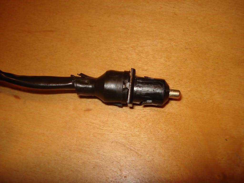 Again, any leads on where to look would be greatly appreciated...I'll keep looking. |
|
|
|
Post by Cruiser on Jun 27, 2011 22:39:00 GMT -6
|
|
Certified Clinician
Currently Offline
Posts: 81
Likes: 0
Joined: Mar 16, 2011 12:32:15 GMT -6
|
Post by philosophydoc on Jun 27, 2011 23:46:42 GMT -6
Dang, Cruiser, is there ANYTHING you don't know???
Many thanks -- just ordered one.
|
|


 ?
?