Senior Clinician
  
Currently Offline
Posts: 103  Likes: 1
Joined: Mar 26, 2014 11:49:43 GMT -6
|
Post by sabotendar on Mar 27, 2014 14:42:54 GMT -6
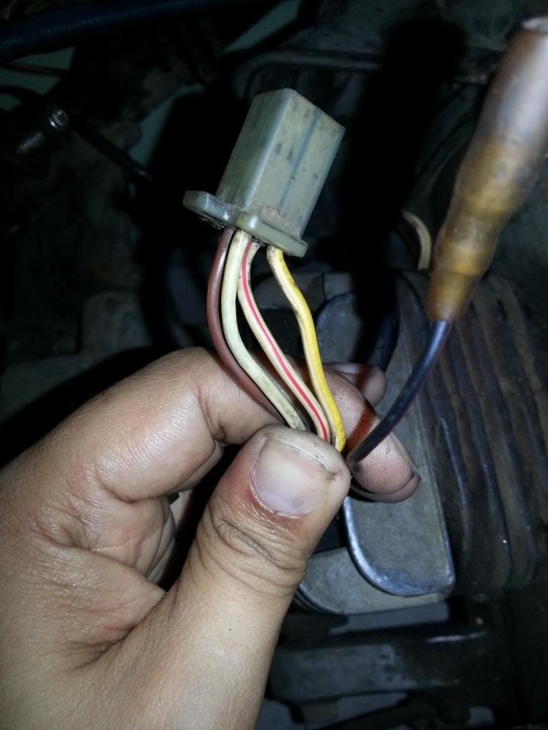
Yea! Let´s see what happens, my stator and pulse coil is similar to this but te color do not match with i have here but the connections plugs is the same:   |
|
Doc's Anything Goes
Currently Offline

Posts: 2,739
Likes: 66
Joined: Oct 23, 2010 19:29:21 GMT -6
|
Post by tvnacman on Mar 27, 2014 14:45:26 GMT -6
even a picture of the stator plug may help . looks like two wires from the ignition switch and 3 off the stator . two from the pulse coil I can understand that . what is the pulse coil voltage ?
John
|
|
Doc's Anything Goes
Currently Offline

Posts: 2,739
Likes: 66
Joined: Oct 23, 2010 19:29:21 GMT -6
|
Post by tvnacman on Mar 27, 2014 14:51:33 GMT -6
are you sure the hand drawn diagram is correct , is the pickup coil two wire ?
John
|
|
Senior Clinician
  
Currently Offline
Posts: 103  Likes: 1
Joined: Mar 26, 2014 11:49:43 GMT -6
|
Post by sabotendar on Mar 27, 2014 15:06:18 GMT -6
The engine not working the carburator is missing and ill be replaced on the next week the battery is replaced and working. Soon i arrive on my home i will do the test and post a picture of stator plug. The scooter worked but when stopped working i dismounted and saw that all the wiring it is rotten and patched however worked anyway.
Thanks to all for the help...
|
|
|
|
Post by Bashan on Mar 27, 2014 20:51:15 GMT -6
This guy Pm'd me and ask me to look at this, I think the guys have it spot on so far. We've got to get some multimeter work on this to figure out what we're dealing with. I have some concerns that need to be cleared up.
1. Get a multimeter on that black wire from the ignition and turn on the key, if it's 12v DC we have a DC CDI system.
2. The way that is drawn it suggests a three phase stator but why are the wires different colors? Sabotendar, are those three wires bundled together in a connector? Do they all go to the rectifier? And just one wire comes off of the rectifier? You need to get us some pictures of these components. You drew a schematic and took a picture. Pull some plastic off of that bike and get us pictures of the wires and components like the rectifier, coil, the more the better. Then I want some meter testing which I will go over at that time.
 3. I'm guessing at this point but if the key grounds the #3 wire that's probably the kill. The odd thing is the systems that kill with the key through the CDI ground CUT the ground and kill the CDI. This one engages the ground which would suggest grounding the coil. Most DC CDI systems cut the DC power to the CDI which kills it. I'm just going to put that on the back burner until we can get some more data. 4. I know one....I know one!! That's the coil wire! 5,6. I gotta go with John on this one....huh? The way it's drawn I gotta say trigger wire(s). It is an AC feed so the current has to oscillate back and forth. But it usually just grounds to the case and then the CDI grounds and that's your other leg of the circuit. It is entirely feasible that you could run the AC trigger circuit right through the CDI, both legs connect to the CDI. I need some AC voltage readings on those wires, I can tell you how to do it. Now a modern CDI doesn't have those connectors so if that is the case we will run the trigger to the CDI, ground the CDI and make sure the trigger has a ground back to the CDI. You probably won't find that CDI or anything like it. We will have to figure out the wires and hard wire it. Oh boy! This sounds fun. At this point we need some pictures and meter readings. Let us know when you're ready. |
|
Senior Clinician
  
Currently Offline
Posts: 103  Likes: 1
Joined: Mar 26, 2014 11:49:43 GMT -6
|
Post by sabotendar on Mar 28, 2014 7:27:41 GMT -6
This guy Pm'd me and ask me to look at this, I think the guys have it spot on so far. We've got to get some multimeter work on this to figure out what we're dealing with. I have some concerns that need to be cleared up.
1. Get a multimeter on that black wire from the ignition and turn on the key, if it's 12v DC we have a DC CDI system.
2. The way that is drawn it suggests a three phase stator but why are the wires different colors? Sabotendar, are those three wires bundled together in a connector? Do they all go to the rectifier? And just one wire comes off of the rectifier? You need to get us some pictures of these components. You drew a schematic and took a picture. Pull some plastic off of that bike and get us pictures of the wires and components like the rectifier, coil, the more the better. Then I want some meter testing which I will go over at that time.
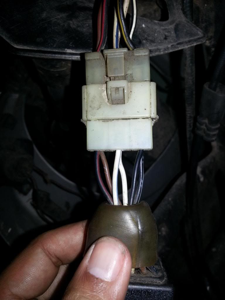
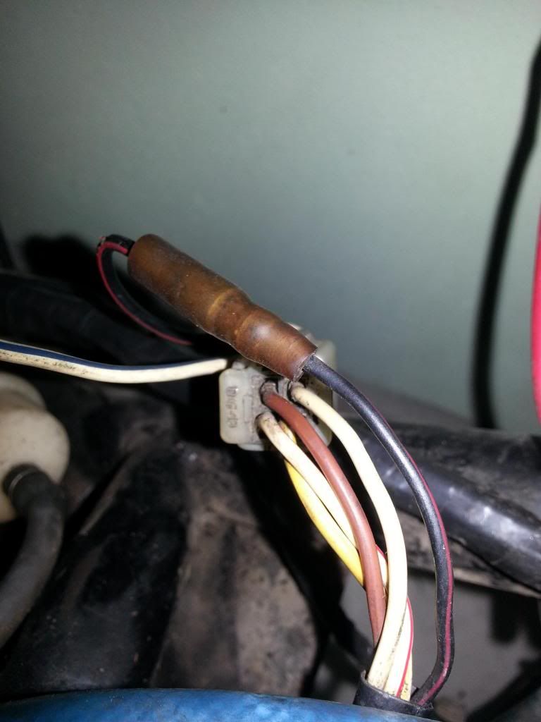
 3. I'm guessing at this point but if the key grounds the #3 wire that's probably the kill. The odd thing is the systems that kill with the key through the CDI ground CUT the ground and kill the CDI. This one engages the ground which would suggest grounding the coil. Most DC CDI systems cut the DC power to the CDI which kills it. I'm just going to put that on the back burner until we can get some more data. 4. I know one....I know one!! That's the coil wire! 5,6. I gotta go with John on this one....huh? The way it's drawn I gotta say trigger wire(s). It is an AC feed so the current has to oscillate back and forth. But it usually just grounds to the case and then the CDI grounds and that's your other leg of the circuit. It is entirely feasible that you could run the AC trigger circuit right through the CDI, both legs connect to the CDI. I need some AC voltage readings on those wires, I can tell you how to do it. Now a modern CDI doesn't have those connectors so if that is the case we will run the trigger to the CDI, ground the CDI and make sure the trigger has a ground back to the CDI. You probably won't find that CDI or anything like it. We will have to figure out the wires and hard wire it. Oh boy! This sounds fun. At this point we need some pictures and meter readings. Let us know when you're ready. I did the tests checking the continuity of the electric circuit with a multimeter starting the from CDI connector to the stator and ignition key off from contact here some pictures:  Stator and pulse plug  CDI connections the colors came from CDI plug is not the same from from scoot circuit plug.   Stator and pulse coil plug.  Wires out from fan. The cables are dirty and after i make clean i have to make another schematics. all the tests are make with the engine not working and ignition key out from contact. I make a mistake from the frist schematics i make the tests with key on contact...so the reads have before with multimeter are wrong...  New schematics. Oh! dont know if the pulse coil have 2 wires out but judging by appearance of wires out from fan case i assume it is. |
|
|
|
Post by Alleyoop on Mar 28, 2014 12:21:46 GMT -6
Well it's a DC CDI so with the KEY ON an NO BATTERY you will get NOTHING. So the First thing you need is a BATTERY otherwise that motor will never start or produce a Spark at the Spark Plug. That Black/Yellow coming from the IGNITION to the CDI should have 12v when the KEY IS ON and when you put in a BATTERY.
Alleyoop
|
|
Senior Clinician
  
Currently Offline
Posts: 103  Likes: 1
Joined: Mar 26, 2014 11:49:43 GMT -6
|
Post by sabotendar on Mar 28, 2014 13:10:50 GMT -6
Well it's a DC CDI so with the KEY ON an NO BATTERY you will get NOTHING. So the First thing you need is a BATTERY otherwise that motor will never start or produce a Spark at the Spark Plug. That Black/Yellow coming from the IGNITION to the CDI should have 12v when the KEY IS ON and when you put in a BATTERY. Alleyoop With the new batery instaled and the key in ON POSITION i receive nothing on black/yellow wire, to test i place the red proof of multimeter on the terminal and the black proof of multimeter on chassis of scoot and the multimeter is set to resistence. When i back to home i will place the multimeter on DC marker and test to see, but to be honest i think i do this test before but i dont remember the result. |
|
|
|
Post by Alleyoop on Mar 28, 2014 13:16:24 GMT -6
Ok, set the volt meter to DC it should read around 12.5-12.7 if the battery is good. If still nothing then check the thin wire coming off the POSITIVE post on the battery going to the ignition it should have a FUSE the FUSE may be bad. So test the fuse on both sides of the fuse to make sure voltage is flowing through the Fuse.
Alleyoop
|
|
Currently Offline
Posts: 0
Likes:
Joined: Nov 23, 2024 6:24:29 GMT -6
|
Post by Deleted on Mar 28, 2014 13:58:03 GMT -6
if its a wire fault or the fuse blew, that cdi may still be good. you said that the wiring looked iffy.
|
|
Doc's Anything Goes
Currently Offline

Posts: 2,739
Likes: 66
Joined: Oct 23, 2010 19:29:21 GMT -6
|
Post by tvnacman on Mar 28, 2014 14:29:06 GMT -6
my money is it is ac cdi , if the stator he posted a picture of is a replacement for his stator . That is not a 3phase stator the paper wraped coil is the ac coil for ignition .
cdi wiring :
Fixed ground
switched ground
power
pulse (could be 2 wire)
feed to coil
crank the engine and read acv from the white wire , let us know .
John
|
|
|
|
Post by Bashan on Mar 28, 2014 14:43:28 GMT -6
I would pull the fan case off if it was mine. Then you should be able to view the trigger coil. Then do as Alley says and get a battery in it. Then we can multi the wires and figure out what goes where. Let's just lose the old CDI and not worry about the colors on it, it's irrelevant. We need to determine what the wires on the bike do and get it hooked up to a modern CDI. Once you have the battery in it we can spin the motor with the starter and test for the trigger, the CDI power feed, and find the kill function. John, what do folks use for a two cycle CDI on a bike like this?
|
|
Senior Clinician
  
Currently Offline
Posts: 103  Likes: 1
Joined: Mar 26, 2014 11:49:43 GMT -6
|
Post by sabotendar on Mar 28, 2014 15:26:01 GMT -6
I will do the test and post tomorrow, and see if that wire goes to the battery fuse...maybe a cracked wire? Even if the CDI is good I will exchange it for a modern one to be easy to replace it in the future  I will open the fan case and take some pics to clarify this enigma and let´s see what happens tomorrow... |
|
Doc's Anything Goes
Currently Offline

Posts: 2,739
Likes: 66
Joined: Oct 23, 2010 19:29:21 GMT -6
|
Post by tvnacman on Mar 28, 2014 15:36:53 GMT -6
I will do the test and post tomorrow, and see if that wire goes to the battery fuse...maybe a cracked wire? Even if the CDI is good I will exchange it for a modern one to be easy to replace it in the future  I will open the fan case and take some pics to clarify this enigma and let´s see what happens tomorrow... If you give voltage readings from the stator while cranking you may not need to pull everything apart . John |
|
Administrator
Currently Offline
Posts: 1,565  Likes: 51
Joined: Jan 27, 2014 13:58:53 GMT -6
|
Post by JR on Mar 28, 2014 16:05:08 GMT -6
Either I'm confused or you are, can you show me a picture of what this is plugged into? I want to see the unit/box itself.


I think the first picture you posted is not a CDI but the R/R and yes guys some CDI's feed from the R/R not the ignition or stator. The Honda Sky is one and with a dead R/R no fire to the CDI.
If I am right as far if this is the CDI and 5-pin then if it can be converted to another CDI think JOG.
www.partsforscooters.com/50cc-2-stroke-CDI
If the unit you posted is in fact the CDI and 6-pin then we think 6-pin the older JOG:
www.monsterscooterparts.com/cdi-50cc-2stroke-qmb.html
When I get back from softball practice later I'll look up those wiring diagrams. Remember google is your friend. 
JR |
|

