Clinician

Currently Offline
Posts: 22
Likes: 0
Joined: Jun 18, 2011 3:14:42 GMT -6
|
Post by noday on Sept 2, 2012 20:32:21 GMT -6
Easy, the eastern diamond back, you are in AL.
8ft would be a record.
I have lived in the deep South for a long time.
When is the barbecue ?
Us rednecks enjoy eatin the really big ones. almost a rite of passage.
always remember, he/she is only there because their food is plentiful.
|
|
Clinician

Currently Offline
Posts: 22
Likes: 0
Joined: Jun 18, 2011 3:14:42 GMT -6
|
Post by noday on Aug 26, 2012 13:36:29 GMT -6
given the no response, I agree justbuggin
|
|
Clinician

Currently Offline
Posts: 22
Likes: 0
Joined: Jun 18, 2011 3:14:42 GMT -6
|
Post by noday on Aug 9, 2012 19:52:20 GMT -6
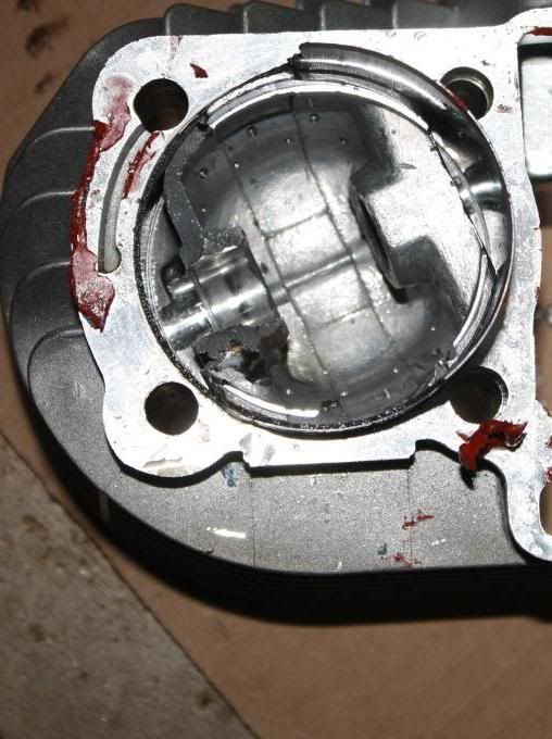
while, from the pics presented, it looks like the case boring was the problem, it is not conclusive.
the piston failed.
I made an educated guess as to why
a very real concern remains as to the bore and piston
was the piston defective ?
until all the relevant details are in, we are chasing Zombies
an early theory is just that, early
a lot of things ?
we disagree....
more information is needed for a conclusion.
|
|
Clinician

Currently Offline
Posts: 22
Likes: 0
Joined: Jun 18, 2011 3:14:42 GMT -6
|
Post by noday on Aug 7, 2012 18:50:10 GMT -6
to clarify what I was trying to say. I am comparing the base of the cylinder to the case. all the pics are taken at different angles and some distortion is present. so one can not take measurements from the pics as there is no measured scale included with in the pics. It looks like, when I compare distances, from cylinder base to case, that the case would impinge aginst the side of the cylinder skirt, when the cylinder was seated. on the cam chain side, it did not. I compared 2 pics. the cylinder base was flipped and rotated so that the same stud holes are in the same position in both pics both are close to the same scale, from center stud hole to center stud hole, left side of the pics   even so, direct measurements are needed perhaps this is just optical illusion |
|
Clinician

Currently Offline
Posts: 22
Likes: 0
Joined: Jun 18, 2011 3:14:42 GMT -6
|
Post by noday on Aug 7, 2012 15:44:28 GMT -6
I disagree with the conclusion of SE and moat above, no disrespect intended in any way.
I agree that the minor irregularities of the case opening is of no consequence and that a perfect fit is not needed.
What I think happened:
The opening was bored eccentric with respect to the studs. there is more metal between the stud holes and bore hole on the side opposite the cam chain passage.
the metal there is thicker than the corresponding space on the cylinder from stud hole to liner/skirt/sleeve.
because the liner has very thin metal in the skirt, the skirt deformed at assembly.
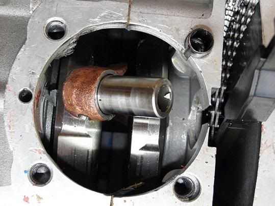
when you look at the bottom of the cylinder, ( in the first set of pics) you see that about half of the cylinder skirt is missing along with a big chunk of the piston side that goes up to the wrist pin hole in the piston.
It appears that the piston hit something and stopped (on a down stroke) and then was pulled apart, taking the missing cylinder skirt with it.
what I think the piston hit was a ridge in the cylinder wall caused by the eccentric opening in the case.
if the cylinder liner skirt had been thicker, it probably would have not seated/mated to the case without extreme force.
to be more certain of this proposed mechanism, more exam of the cylinder and piston is needed, along with measurements of the suspect area.
a retrieval and exam of the missing pieces of both the piston and cylinder skirt may give more light.
so I will leave my proposed theory up for critical discussion.
perhaps some one else sees something in the pictures that I do not and has a better explanation
|
|
Clinician

Currently Offline
Posts: 22
Likes: 0
Joined: Jun 18, 2011 3:14:42 GMT -6
|
Post by noday on Aug 5, 2012 7:29:46 GMT -6
Hey GTi how about some more pics of the cylinder and engine case opening ?
can you get the piston out of the cylinder ?
how did the cylinder block fit into the case opening ?
sorry about the loss of your engine. I would be really bummed out too.
|
|
Clinician

Currently Offline
Posts: 22
Likes: 0
Joined: Jun 18, 2011 3:14:42 GMT -6
|
Post by noday on Aug 4, 2012 6:12:06 GMT -6
I think that by hiding/deleting the thread, you do the forum and readers a dis service.
quite few of the posts were out of line.
at the same time, I still think the mechanism of failure is undecided.
we all learn by knowing how engines fail. when we see good info about failures perhaps mistakes, we can try to avoid having the same thing happen.
my guess based on GTI's few pics is that the bore and crank were malaligned, but that remains unclear.
the bore should index from the studs and not from case opening.
another point is: are these large cylinders with very thin base skirts prone to failure ?
I for 1 would like to see more pics of the failed engine.
was the crankcase opening bored eccentric ?
did the thin cylinder base skirt deform because the opening was eccentric ?
|
|
Clinician

Currently Offline
Posts: 22
Likes: 0
Joined: Jun 18, 2011 3:14:42 GMT -6
|
Post by noday on Sept 18, 2011 5:32:31 GMT -6
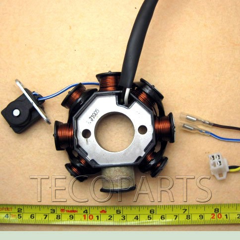
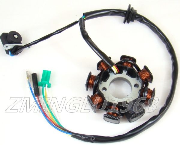
that stator was just the cheapest one that popped up in a quick ebay search. besides the hole spacing, another thing to check is the angle of the mounting holes v the trigger pole. that ebay listing looks the same as your stock stator, to me. when you draw a line from 1 hole to the other, what is the angle of the center of the trigger pole.? will this affect the timing of the trigger pulse ? some of the different stators have different angles of orientation. my guess is probably no, as long as that pole is energised at the time of triggering. this is one example that has a different mounting hole orientation and probably would not work properly  here is another that looks like the right orientation. costs a bit more & has hole spacing on the listing.... but can't see the wiring hookup. ships from US so less time for delivery cgi.ebay.com/ebaymotors/Magneto-Stator-GY6-50cc-125cc-150cc-Moped-ATV-Go-Kart-/190572603675?pt=Motorcycles_Parts_Accessories&hash=item2c5f03291b just some different things to look at and think about |
|
Clinician

Currently Offline
Posts: 22
Likes: 0
Joined: Jun 18, 2011 3:14:42 GMT -6
|
Post by noday on Sept 17, 2011 7:11:47 GMT -6
edit: your stator makes no sense to me.... & it now makes sense why only 1 specific RR works another option, the below ebay listing is in pounds or about $20 US for this stator looks closer to the TT KTM and should convert with minimal problems www.ebay.com/itm/8Poles-GY6-50-Moto-Engine-Sparking-Magneto-Stator-Coil-/250869207333?pt=UK_Motorcycle_Parts&hash=item3a68f85125 yes it makes sense. edited: probably can get rid of the green (ground ) wire on this stator. after conversion... don't think that it is needed for the CDI trigger pulse also you can see why winding are added to a pole in the TT guide... a 12 V DC conversion has to end up with all things run from the battery and the battery charged from the stator/RR, just like a car alternator/battery system |
|
Clinician

Currently Offline
Posts: 22
Likes: 0
Joined: Jun 18, 2011 3:14:42 GMT -6
|
Post by noday on Sept 10, 2011 4:31:05 GMT -6
this is one of those projects that is very simple in concept.....But when you get to the implementation, you have to stop and scratch your head at every twist and turn. as far as I can tell, Trailtech just makes the 1 universal RR with different connectors. I think they are designed for ATVs and motorcycles, not for GY6 based scooters. the universal RR you found is probably a TT knockoff Yes, it is confusing.... very. trailtech.net/media/electrical/dc_conversions/ktm_dc_conversion.pdfpart of what makes this example more confusing is the addition of windings to one of the poles. the key point is floating & insulating the centertap. after that it is a matter of making sure the two wires (white and yellow) are connected to the ends of the windings and protected from rubbing on the flywheel....... to decrease any future confusion, I would replace the white wire with a yellow one, so that you have 2 symmetrical yellows. should be simple as pie, but that went out the window months ago. I think you are on the right path. good luck today |
|
Clinician

Currently Offline
Posts: 22
Likes: 0
Joined: Jun 18, 2011 3:14:42 GMT -6
|
Post by noday on Sept 9, 2011 18:41:34 GMT -6
I think that the first diagram is probably wrong..... the center tap should be grounded rather than one end.
a center tap is used to provide a "neutral" point in a coil (or transformer) for comparing the 2 ends or to get different voltage outputs depending on the coil/winding count ratios
in that diagram were true, the yellow connection to the coil would be ground and you would only see voltage on white.
we know that is not the case.
scooter 6 and 8 pole stators have odd numbers of charging poles, 5 and 7, and you can not substitute white for yellow or visa versa. The "other" pole triggers the CDI.
so stator output is not "balanced" on white and yellow compared to ground. the output of white v yellow is 2v3 or 3v4 because of the odd number of poles
yellow powers the AC lights and auto enricher as well as the RR
full wave "floating" stator output is more or less comparable to 240 V AC residential power and is balanced
if you measure voltage from either wire, measured to ground, you get half the voltage compared to measuring wire to wire.
the CDI feed is from a circuit separate from the charging circuit, so a ground in that circuit would have no effect on the charging circuit.
yes, no more yellow and white, just 2 yellows
|
|
Clinician

Currently Offline
Posts: 22
Likes: 0
Joined: Jun 18, 2011 3:14:42 GMT -6
|
Post by noday on Sept 8, 2011 17:58:21 GMT -6
Thank you for the update.
I am really sorry to hear that.
As you would probably guess from my other thread, I have been foolin around with this for a while, but on a 50/72cc scoot, 6 pole.
In threads on Dawg and Totalruckus others also blew the RR.& I never could quite figure out what they did wrong. the threads are several yrs old & the posters no longer around/active.
part of the problem is that there are at least 2 and probably 3 different 8 pole stators for the GY6 150. By rumor, some of the Taiwan scoots use a 2 trigger pole version with full wave. have never had a chance to look at one live to see the details.
I have seen threads where several people have purchased new 150 engines and the 8 pole stators required different RRs. The lack of documentation for both Stators and RRs makes for a crap shoot much of the time.
there are also some full wave mixed AC DC RRs for sport bikes but they are only rated for about 6 to 7amps DC
All in all, most confusing.
I think the best way to trouble shoot is probably to fuse all RR wires around 5amps or so while testing
It would be nice to have an old crank & crankcase with the crank turned by an electric motor to test different configurations before connecting to the scooter wiring harness.
good luck with the project. I look forward to future updates.
|
|
Clinician

Currently Offline
Posts: 22
Likes: 0
Joined: Jun 18, 2011 3:14:42 GMT -6
|
Post by noday on Sept 7, 2011 16:21:09 GMT -6
looks like good progress.
just wondering if you have an estimate on how much the radiator will drop the oil temp ?
glad the electric part is working out too.
|
|
Clinician

Currently Offline
Posts: 22
Likes: 0
Joined: Jun 18, 2011 3:14:42 GMT -6
|
Post by noday on Sept 6, 2011 13:19:26 GMT -6
that 1 amp fuse is inline with red to the switch. looks like protecting the switch from arch damage.
I think the main goal of the circuitry is to protect the battery from draw down when the engine is not running. (sitting for days or weeks)
you don't need to monitor the oil temp if the engine is not producing heat (running)
this was designed for a car dash so you have to keep that in the back of your mind when thinking about how it was intended to work.
you can always hook the gauge up to just a battery and the sender with the sender in hot water. leaving white free
looks neat
|
|
Clinician

Currently Offline
Posts: 22
Likes: 0
Joined: Jun 18, 2011 3:14:42 GMT -6
|
Post by noday on Sept 6, 2011 11:36:11 GMT -6
my first guess is that red is a low amp draw that turns orange off and on. (since orange is always connected to  ) 12V) designed to not overload the key switch , in terms of amp draw, & to turn device off when engine is off so that battery is not drained. this implies that the device itself may use a significant amount of current ? |
|

