Clinician

Currently Offline
Posts: 38
Likes: 0
Joined: Jul 15, 2010 10:29:12 GMT -6
|
Post by tk3000 on Jul 16, 2011 23:21:23 GMT -6
It is crazy that the thermostat was simply absent or non-existant; that certainly explain at least part of the cooling issues. I will check the other one I have to make sure it has a thermostator inside the thermostator housing. tk |
|
Clinician

Currently Offline
Posts: 38
Likes: 0
Joined: Jul 15, 2010 10:29:12 GMT -6
|
Post by tk3000 on Jul 16, 2011 5:05:49 GMT -6
Using copper should be no problem. I have seen copper used by other people in their scoots with no adverse affects. I would assume the copper would ok too since it is used to carry all sorts of fluids and chemicals, also its specific heat is lower (copper's specific heat is lower than aluminum's specific heat). I happen to have two 250cc bikes both in my garage for some time, and I have been away for most of the time lately, so no many chances to work on them or ride them lately; but I hope to change that soon. I haven't looked at the one that has a vacuum leak yet (maybe cracked manifold or cylinder head gasket damaged) but I hope to check it out this weekend. Nonetheless I have been working on the cooling system of the other ones (woody black 250cc, storm as well): I fabricated an underneath plumbing contraption out of aluminum pipes and fitting as shown below:  Partial setup shown below, red high-temp permatex gasket maker was used to the water pump housing, inside of the pump and impeller were checked and cleaned and seemed to be ok.  After assemblage, cleaning and adjusting of carburetor and then refilling of the coolant fluid (50% coolant, 50% distilled water) the bike started right up, but it was overheating very fast and with lots of intensity. On occasion of refilling the coolant I burped the system of any pockets of air by leaving it idling for a while with the coolant pressure valve open and rocket the bike help in the process. But the main radiator was completely cool (lower radiator), the upper radiator got hot after a 5 minutes of engine running), the copper pipes underneath were pretty hot, and then engine case and specially the rubber body of the enricher on the carburetor were very hot very hot indeed. So clearly not coolant was circulating up to the lower radiator (the larger and main one) and maybe not even circulating at all to some part of the engine. So I decided to take a closer look at the thermostat; removed, opened it up, and took a look inside, as shown below: 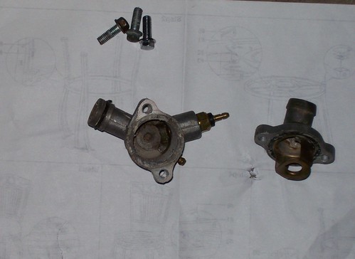 I was expecting to find some spring loaded mechanism inside the thermostat housing that would open or shut the flow of coolant to the engine depending on the engine temperature (shutting the flow in order to allow the engine to reach operating temperature for instance), but found nothing. Is that the way it should be? Thanks, tk3000 |
|
Clinician

Currently Offline
Posts: 38
Likes: 0
Joined: Jul 15, 2010 10:29:12 GMT -6
|
Post by tk3000 on Jul 1, 2011 23:55:49 GMT -6
Hi tk3000. How many miles on your scoot? The compression specs for this engine is 213 pounds @ 600 rpm. A leaking head gasket could cause both lower compression and an oil leak. Check the area around the head gasket closely. This engine is prone to cracking of the intake manifold which can cause a lean condition. It sounds like the engine is starving which may be an intake manifold leak. Thanks Cruiser! It has less than 40 miles, it is a storm 250cc I bought some time ago (about 9 months ago), but I haven't been around to work on it, so it was seating in my garage most of the time. It has two radiators, and the plumbing underneath was leaking so I also built some contraption out of copper pipes and fittings to replace the original plumbing underneath (that is made of out soft and brittle aluminum) as shown below:  Would you know about any contraindication about using copper pipes in such setup (with automotive coolant)? I will check the head gasket and the intake manifold next week. Hopefully, it is just the intake manifold! I will let you the findings. tk3000 |
|
Clinician

Currently Offline
Posts: 38
Likes: 0
Joined: Jul 15, 2010 10:29:12 GMT -6
|
Post by tk3000 on Jul 1, 2011 20:08:12 GMT -6
Hello Folks,
I know my way around the gy6 4-stroke engine and 2-stroke engines, but I am not very familiar with the CN250. Valves seems to be properly adjusted, installed new carburetor just in case since I suspected that maybe it was a carburetor related issue (enriching circuit or cut-off valve) and cleaned all the passageways and galleries, renews all vacuum lines/fuel lines and clamps, coolant and cooling system seems in good shape, etc. When I first turn the engine on and try to open the throttle it starts to sputter and wants to die even I try open the it slightly, after about 15 minutes of the bike running (idling) it starts to get more responsive and seems to respond to throttle input more or less ok. But still it seems to be restricted somewhat since it does not want to go fast enough (I did not try in a long stretch though). I tested engine compression with a cold engine and obtained around 100 PSI which at first seems low. Also to add up to the problem there is an oil leaking underneath the engine (few drops of oil that manifest themselves mostly when the engine is running and is still warm).
One possibility that I am considering is that the the engine case is not properly sealed (I verified the torque in some bolts, and they seemed ok; but I am not sure if I check all of them) and thus it is leaking vacuum and also some oil, and once it gets warmer the metal would expand thus acquiring better sealing which would then help minimize the sputtering and stuttering that tend to happen during the first 10 minutes of engine running whenever I would open the throttle. Also the oil leakage gets worse whenever the engine is running or still hot, the oil leakage does not seem to originate from underneath the engine. Is there any spot on this engine were the oil leaking and any vacuum leaking would be more likely to originate from; or maybe there are another root for such sudden death of the engine whenever I try to open the throttle for the fist 10 minutes of running the engine? Any input would be appreaciated.
tk3000
|
|
Clinician

Currently Offline
Posts: 38
Likes: 0
Joined: Jul 15, 2010 10:29:12 GMT -6
|
Post by tk3000 on Apr 24, 2011 22:25:44 GMT -6
I was awakened by thunder storms and couldn't get back to sleep. So I picked up a copy of model airplane news. Radio controlled planes and helicopters is one of my other expensive hobbies. Anyway I came across an add for servo motors. then I got to thinking. I wonder If I could replace the throttle cable with a servo and driver. Now the reason I'm thinking of this is because when I changed the carburetor to a 24mm the throttle cable was not long enough and I had to modify the cable bracket and move it closer to the operating linkage. If I wouldn't of been able to do this I would have to replace the cable. If it had a servo it would have been as easy as loosening the clamp and extending the cable. Any thoughts on this? Roy It does not seem to be worth for such small vehiclea and it would add another point of failure since it would require power source off the votalge regulator (if there is something wrong with the D/C voltage you would lose throttle). If the battery was too weak you would need to kick start it and slightly open the throttle, but there would be no throttle response. Besides it would be more likely for the small serv motor to fail than for the cable to collapse. tk3000 |
|
Clinician

Currently Offline
Posts: 38
Likes: 0
Joined: Jul 15, 2010 10:29:12 GMT -6
|
Post by tk3000 on Apr 22, 2011 23:39:37 GMT -6
dude i have the same scooter, im going to give you the "run down" what to do to this thing so it runs like a champ. i got mine basically brand new for $300. it had a number of problems and i was a noob when i first got it, believe me if you do this you will save yourself problems in the long run. replace vacuum fuel pump with a 3/8" fuel line/w manual on/off valve replace intake manifold ( the current manifold will crack) replace as many lights as you can with leds REMOVE the alarm asap (it can drain your battery randomly) be patient when you re-add new coolant, the bike has dual radiators so itll take a little bit before it fully 'burps" itself of air. heres how my storm looks 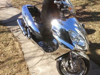 Mine is identical to yours (I have two identical models with different colors: one is chromed like yours, and the other one is wood black). It is an awesome bike, and in spite of some initial problems and issues the built qualit is decent and above the average in terms of a Chinese bike. (Too bad the winter in Michigan is long and severe which really shorten the riding season). It is the ultimate platinum experience. tk3000 |
|
Clinician

Currently Offline
Posts: 38
Likes: 0
Joined: Jul 15, 2010 10:29:12 GMT -6
|
Post by tk3000 on Apr 22, 2011 4:18:19 GMT -6
It's not the propanes fault. The plumbers kit you are using is equivalent (roughly) to a #8 tip when you should be using a #14. Wish I could loan you mine. If you had help and another torch like yours, you would probably have enough heat to do it easily. Good luck. Thanks for the heads-on, I bought a torch of the proper size and what a difference! I bouught the following at harborfreight: www.harborfreight.com/electric-start-propane-torch-91061.htmlThe bigger flame transfer much more heat really fast (welding is a kind of new endeavour for me for the moment being). But the hole on the aluminum tubing (used for the cooling system) is too big (bigger than a dime) and also asymetric and disform which make difficult to use surface tension alone to cover the hole. Would there be a heavy duty aluminum screen which would withstand the heat that I could use to patch the hole andthen apply the rod (durafix)? To make things worse the aluminum tubing itselt seems to be made of a weak aluminum alloy (that will also collapse with some extra heat). thanks! tk3000 |
|
Clinician

Currently Offline
Posts: 38
Likes: 0
Joined: Jul 15, 2010 10:29:12 GMT -6
|
Post by tk3000 on Apr 12, 2011 0:35:03 GMT -6
Thanks for the responses. Propane does not quite cut it for the aluminum rods; after a very long time of heating the best result would be a brittle, breakable, failing and faulty weld. I will try with the propane torch, and it does not work well enough I will try with a proper torch for mapp gas.
|
|
Clinician

Currently Offline
Posts: 38
Likes: 0
Joined: Jul 15, 2010 10:29:12 GMT -6
|
Post by tk3000 on Apr 11, 2011 14:51:35 GMT -6
Hello,
I have a propane kit (the pumbers type) that came with with a torch. I will wedge some alluminum pipes used for coolant distribution and heat exchange, and was wondering if it would be ok to use the propane torch with the mapp gas.
thanks,
tk3000
|
|
Clinician

Currently Offline
Posts: 38
Likes: 0
Joined: Jul 15, 2010 10:29:12 GMT -6
|
Post by tk3000 on Nov 5, 2010 0:26:22 GMT -6
Ok let's help each other out here, seriously man I actually thought about removing all of that plumbing, seeing as I have the same exact chrome scoot as you. These bikes have been stting with old coolant for 4 years, which equals rust+corrosion. I was going to say to use some silicone adhesive but then it might not retain pressure that is needed. Those pipes specifically worried me because they are terribly corroded, I can even imagine insde the litle bends and crevices. I would go to my local home depot or lowes and purchase that copper plumbing pipe( straight with no curves) and I pretty much gurantee that nice little mod will fix your issue and infact improve your cooling system. Ok now its your turn lol. Today I accidently fell on my airbox as I was cleaning the carb, I'm intrested in maing just an open air filter, is there a certain way I have. To position it ? Help me out. And could you please snap a pic of your valve adjustment because my bike is really hard to start, and do you know where the ground wire from the battery actually connects to the frame ? I never adjust the valves for such a bike, but it should be simpler than with a gy6 since you don't need to remove the cylinder head to do so (I have done it in my 150cc gy6, and had to remove the head). But you probably will need to remove the CVT case in order to put the piston in the TDC (Top Dead Center Position). Below are couple of links related to such subject: www.ch250.net/techtips/5.htmwww.ch250.net/techtips/5.htmAnd if you do a search in this forum you probably will find how-tos related to valve adjustment for the CN250) I am not sure how approach using a free flow filter air flow for such a bike since emission lines, breather tubes, and vacuum lines are hooked up to the airbox and other components. I installed a free flow air-filter in my 2-strokes, but that is a completely different beast. And since you are at the carburetor you may want to also remove the air-fuel mix screw (locate at the bottom of the carb on the intake side) clean it and adjust it (I found out that 1200 degrees adjustment should be good for such bike: remove and clean it, then turn it 1200 degrees clockwise in) Our scooter use a CN250 clone engine and parts (Honda Helix) so there are plenty of information and documentation available. And lots of other Chinese scooter use the same engine and ancillary parts (carburetor, starter, air-box, etc). tk |
|
Clinician

Currently Offline
Posts: 38
Likes: 0
Joined: Jul 15, 2010 10:29:12 GMT -6
|
Post by tk3000 on Nov 4, 2010 23:31:47 GMT -6
Sorry for the absence of response, I have not had time to work on my bike s lately. Actually that is my seconds 250cc I bought a 250cc Chrome and soon after I bought a 250cc Woody Black One (yeahh, I couldn't resist the deal and also the opportunity to intervene in such machines). Interesting enough even though they are the same model and same year (just different color) there are some differences mainly in the cooling system arrangement (maybe due to parts availability, etc). Thanks for the info about aluminun welding. Is Durafix the commercial name of the rod to solder aluminum and can I buy it at any local home center store (homedepot)? And can I use a small buttane torch such as ones used to solder copper pipes, for instance, to get the job done)? Below are some pics of the main difference between the Chrome and Woody Black scooters, the disposition and arrangement of the cooling system. On the Chrome one I fill up or top up the coolang through the frontal radiator (radiator cap located on the radiator itselt). On the Black Woody there is no such thing as radiator cap on the radiator itself, but an extension hose that goes up afixed nearby the gas tank whereon there is a fitting for a radiator cap and that where the coolant can filled up or topped up. Other than that, all in all, seems to be about the same scooter 250cc Woody Black coolant system converging point: 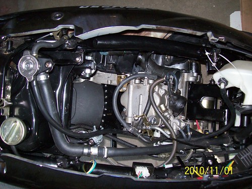 250cc Chrome coolant system converging point is frontal radiator: 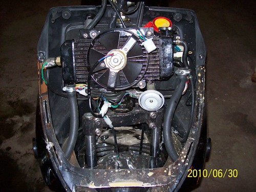 (note radiator cap on radiator itself) 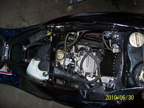 (extra plumbing apparatus for the coolant system absent in the Chrome one) The 250cc Woody Black one is certainly more convenient since there is not need to remove the front panel/fairings, and access it is just as easy and straightforward as accessing the fuel tank. As far as leakage goes I haven't had a change to thoroughly investigate the situation, so the only obvious point of failure identified so far was the aluminum plumbing, and since the system is depleted of coolant (I drained all of it, mostly through the hole in the aluminum plumbing itself) I can not easily verify any other source of leakage. But I intend to overhaul the hole thing, including install new coolant hoses (the original ones seems of decent quality but I will renew them anyway), check and clean some parts (water pump seals and impeller, plumbing, etc). Below are some extra pics of the commencement of the Woody Black coolant overhaul process: 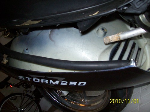 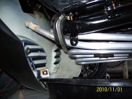 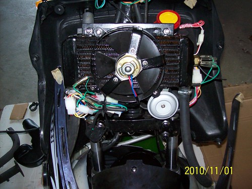 tk |
|
Clinician

Currently Offline
Posts: 38
Likes: 0
Joined: Jul 15, 2010 10:29:12 GMT -6
|
Post by tk3000 on Oct 31, 2010 14:27:00 GMT -6
Recently I identified a previously very small hidden leak (given its tiny small proportion) that got much worse. The spot that is leaking is the aluminum plumbing underneath the bike: when I opened the radiator cap the pressure builds up inside and the tiny small hole/segment on the pipe that was leaking showed all its leakage potential. Welding light aluminum does not seem work most of the time, so the first thing that came to mind was JB-Welder, but I am not sure about how well it will hold (and for how long). The plumbing is designed and arranged to maximize the surface area of contact with the air as shown below: 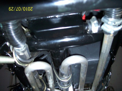 Any insights on other ways to approach such issue would be appreciated. tk3000 |
|
Clinician

Currently Offline
Posts: 38
Likes: 0
Joined: Jul 15, 2010 10:29:12 GMT -6
|
Post by tk3000 on Oct 9, 2010 2:50:16 GMT -6
Rich, sorry for the delay in my follow up. I am posting the video that I took on occasion of the electrical overload caused by the deregulated voltage regulator (I happened to have my camera at hand on occasion...). Well part of the reason for such electrical overload and the burn down of the lamps and other potential electrical devices was because the voltage regulator wasn't doing its job of stepping down the voltage for the lighting circuit. The voltage dedicated to the lighting circuit is too high (specially when there is not much load on the system, in the video above my headlights were disconnected), and thus the voltage regulator steps down the voltage by means of shunt the excess of current to the ground then converting and dissipating it into heat. And as far as wiring I tested and retested everything: the resitance accross the wires and with the ground seems to be ok (about 0.03 ohms). During measurements I flexed, jolted, and shaked the wires without noticing any difference or lapse on the measurement readouts. I also removed the entire main harness and cut the wire looms, and found nothing visibly wrong. Since the gang connections are the weakest link I replaced some of them with much better connector. I also soldered some joints that were simply spliced together. Looking at hindsight I should have replaced the wires with better ones as you suggested. As of now, at an idle of around 1500 rpm the bike is able to keep up with the lighting circuit but the lights are sort of dim, but when I am riding it the intensity of the headlights is more or less ok. I replaced the OEM 18 watts H4 headlights (two bulbs) with halogen ones (they are also 18 watts, but halogens). As far as voltage for the lighting circuit: at idle => 10 AC Volts when the headlights are OFF, and around 6 AC Volts when the headlights are ON. At first it makes sense to have voltage drop since the headlights introduces a heavy load on the lighting circuit, but I was wondering if such measurements are ok or not. Thanks, tk |
|
Clinician

Currently Offline
Posts: 38
Likes: 0
Joined: Jul 15, 2010 10:29:12 GMT -6
|
Post by tk3000 on Sept 25, 2010 1:44:52 GMT -6
I don't have a specific questions because I am not sure about what the root or roots of the problem are, and apparently there are a multitude of issues going at the same time, and all such issues are electrical related. It stems from the fact that quality of the harness and the very soft copper connections (made of pure copper) and other components of the system are rather low and very often the wires are simply hold and hanged on poor soldered connections without any type of basic mechanical relief mechanism whatsoever. To make things worse I bought a voltage regulator that simply fried all the bulbs in my AC lighting system because it failed to simply regulate the voltage for the lighting circuit.   The secondary path to the ground that I created solved the starting issue for good, and never had any sign of overheating wire in the perimeter of the stator again. And as I mentioned before the problem not only is of electrical nature but it is also is not circumvented to any single part, region, or system, but is spread throughout different parts. Sometimes I have to ask myself if something whose quality is so poor is worth the time and effort... Anyhow today I found some time to work on the bike again, and found out another problem the light switch simply wasn't bridging the yellow (live wire) with the other wires (for low and high beams), so I fixed that small thing and now there is voltage going to the main headlights (but it is too low). I am testing from different points (or with different circuits connected or disconnected to the system) of the in the system, as follows: The main problem more or less isolated now: 1) very low voltage coming from the stator from the yellow wire when the stator is connected to the main harness and voltage regulator => about 8 to 9 Volts AC (normal idle) seems very low specially considering that there is no load from the lighting system; 2) But when the stator is not connected to harness at all, the voltage coming out of the stator (yellow wire) is around 20 Volts AC; 3) When the Yellow wire from the stator is connected to the Main Harness but the main Harness (and by extension the stator) is not connected to the voltage regulator the voltage measured is 0 Volts AC. Maybe a wire connected directly from the yellow wire coming from the stator to the voltage regulator could be a possible approach, since the the yellow wire inside the main harness may be crushed, crunched and/or frayed. With every connected and the bike running: DC voltage for the charging system is ok (13 to 14 volts dc), and AC Voltage going to the CDI and Ignition system is ok. Sorry, but I went above my one paragraph (or few lines) quota since I had more or less explain all the issues that cropped up together out of Roketa/jmstar standard of quality concerning the electrical system of the fiji150cc. But you should only take into account the paragraph above, it nails down the problem as it presents itself now. |
|
Clinician

Currently Offline
Posts: 38
Likes: 0
Joined: Jul 15, 2010 10:29:12 GMT -6
|
Post by tk3000 on Sept 20, 2010 14:02:17 GMT -6
Something with the stator is not right? Should have more AC than what you are saying, look at the system analyis above. What voltage regualtor did you use? =>Most of the measurements were made at the Voltage Regulator end with the VR [Voltage Regulator] connected to the wires (gang connector) that comes off the harness and that are originated from the stator. But if I disconnect the gang connector of the VR (so that the measurements from the stator is not affected by any discrepancy or irregularity off the RG circuit) and measure the AC Voltage coming from the stator at the gang connector that is supposed to be hooked up to the VR the voltage that I obtained is the following: the readout is about 45 AC volts (Idle) and 65 (high rmp). In other words that is the voltage that is generated at the stator and sent to the VR. New Voltage regulator that I bough off ebay: cgi.ebay.com/ebaymotors/ws/eBayISAPI.dll?ViewItem&item=120622960351&viewitem=&category=43976(some 150cc uses a bigger one, but my fiji150cc uses the smaller one similar [if not compatible] with the ones used on 50cc) Need to remember the engine is mounted in a way by bolts going through hard rubber bushings which actually isolate it from the grounding system, it must have a good ground. => I realize that, that is why I created a second path to the ground (connecting the frame directly to the engine case) => Possibly a frayed or partially damaged/deteriorated ground wire were causing some smoke on the ground going to the engine case (fan cover bolt) and also caused serious difficulties and hesitation in running the electrical starter. Since I created such alternative heavy duty path to the ground connecting frame directly to to the engine case I never had a single episode of smoking in such ground wire (fan cover bolt) and the electrical starter now always works flawlessly. The Bali wiring diagram in the tech section works for a lot of scooters so you can probably use it as a reference. => Thanks for the insight and the links ( I will take a closer look at them). =>To make things worse all my headlight bulbs were burned out by the other brand new Voltage Regulator that I installed. The yellow wire that comes from the stator to the VR is for the lighting circuit. The yellow wire goes to the voltage regulator because the AC voltage still needs to be regulated or you would blow every bulb on that circuit as soon as the engine was revved. So it seems that such new VR simply did no regulated the AC Voltage directed to the lighting circuit. Such new voltage regulator (a black one advertised as gy6 150cc Voltage Regulator on ebay) probably was bad, so bad that caused wreak havoc in the my scooter electrical system (all bulbs went south). The previous one was a gray one bough sometime ago (and also advertised as been compatible with gy6 150cc). tk |
|

