|
|
Post by royldoc on Jun 21, 2011 9:07:45 GMT -6
Here are some photo's of the axle and axle tube. 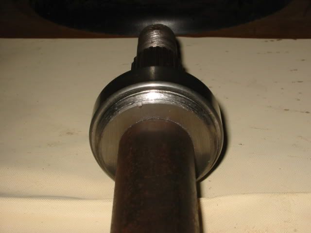 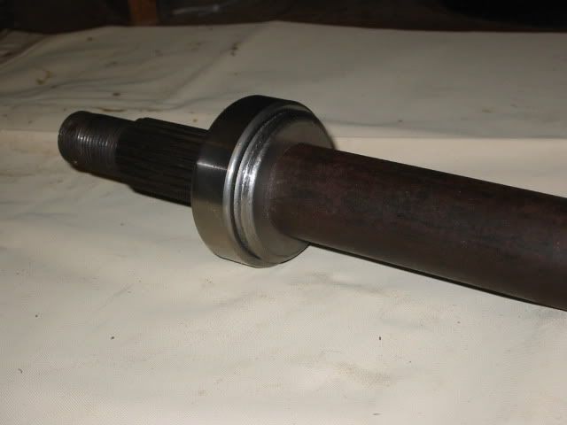 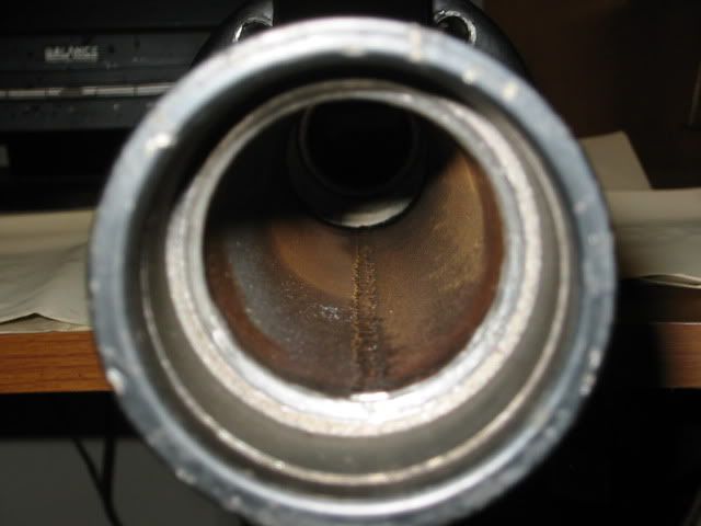 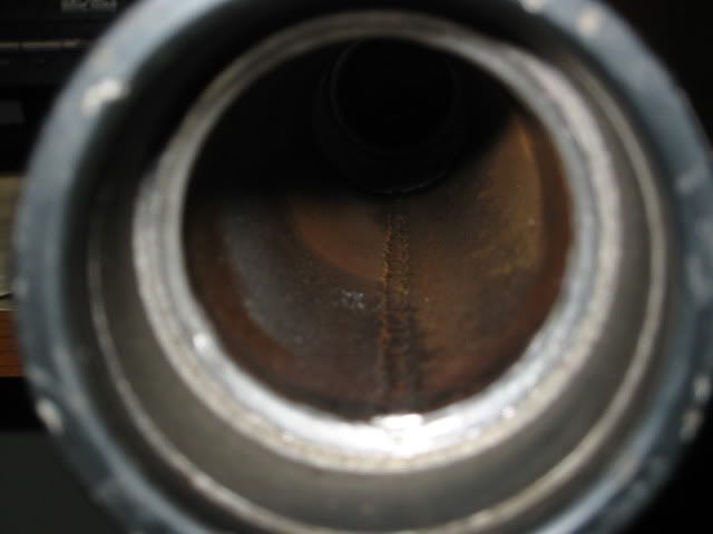 The ones of the inside of the tube look a little blurry, I think it is reflection from the flash. I need to figure out how to keep this from happening. Maybe use the same method as moving out problem, just put a screw on both sides of the ring. Roy |
|
|
|
Post by royldoc on Jun 20, 2011 12:31:38 GMT -6
Thanks ally, I don't think my slide hammer would have done it. the left side was in really tight. the right side came out with two hits. I didn't see any thing wrong on the left but the right had a lot of metal dust in the tube. The ring on the axle behind the bearing was eating into the tube. will post photo later. I have to go to work now.
Roy
|
|
|
|
Post by royldoc on Jun 20, 2011 11:56:01 GMT -6
I got it. Several swings with a B.M.F.H. didn't work, so I got a bigger M.F.H.. I hit that sucker so hard it knocked the trike off the jack stands. I had to move fast. I dropped the hammer, grabbed the axle tube and balanced it while I kicked the stands back under it. I ran out of time will post photo's of axle and tube later.
Roy
|
|
|
|
Post by royldoc on Jun 20, 2011 9:39:13 GMT -6
I need to know how to get the rear axles out. Before I go gungho and use my B.M.F.H.
Roy
|
|
|
|
Post by royldoc on Jun 18, 2011 13:55:31 GMT -6
I got mine apart today splines aren't rounded off but the hub is sloppy loose on the axle. tightened the crown nut some more. I'm gonna have new hubs made with tighter tolerance.
Roy
|
|
|
|
Post by royldoc on Jun 16, 2011 0:06:01 GMT -6
That is what happened to mine. I don't think the splines are bad yet. I haven't had time to tear it apart and fix yet. The left wheel is wobbly I haven't determined if the bearing is bad also as the axle wobbles with the hub. I Will know when I get it apart. Hopefully the bearing company we use at work will have them and I wont have to order. Also instead of the floating ring I plan on using thrust bearings. If the axle and hub are bad I will have the shop make me some of better quality.
Roy
|
|
|
|
Post by royldoc on May 8, 2011 6:20:47 GMT -6
I haven't been able to work on the scooter for a while. The rocker arm assembly failed on me. This is what happened. 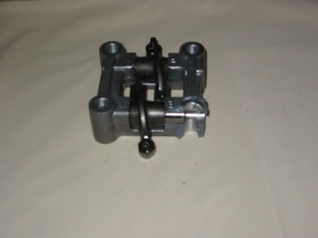 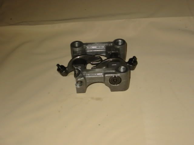 It was torqued at 15 ft lbs. I think it was a bad casting. I am in the process of tearing the case apart to get the broken bits out. I also have other stuff to get done, so I haven't had a lot of time to work on this. Roy |
|
|
|
Post by royldoc on May 1, 2011 12:34:40 GMT -6
I finally got every thing Installed except for the O2 sensor. I Tried to start the engine it wants to start but will not run. I am having trouble installing the software on my lap top. some files out of date or missing. I also tried to download software from the website but I get a pdf that adobe can't open. I'm going to call Matt @ Ecotrons tomorrow. I think it will run once I get the software loaded and can tune it. 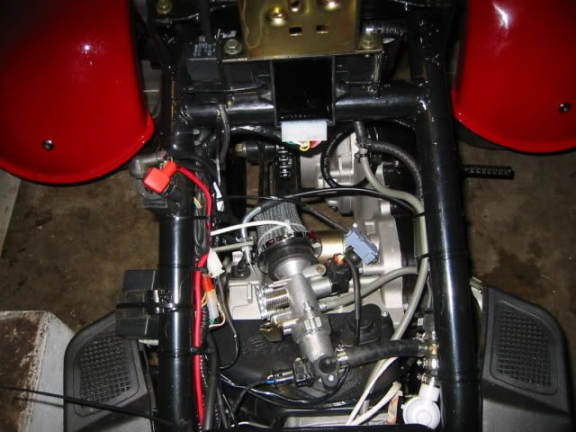 I mounted the ECU and relay to the frame. I had Just enough room behind the seat bucket. I drilled out the vacuum petcock and installed a manual valve. 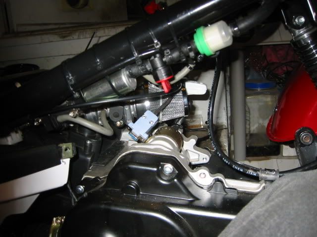 It will run (FAILURE IS NOT AN OPTION) ;D Roy |
|
|
|
Post by royldoc on Apr 26, 2011 9:19:35 GMT -6
Good news, I don't have to go to st Louis after all. the company we got the machine from hired a machine moving company to do it.  I spoke with Matt at Ecotrons. He said that power consumption of the system should not be a problem. The charging system output is about 60w He said they run this system on 50cc engines and the only problem is at prolonged idle it may not charge. If the engine runs at more 2k rpm it should have enough power. I also asked what the difference in their cdi and my cdi is.His answer is that most cdi's control the spark advance and will conflict with the ECU to control the spark. Their cdi does not control the spark. I will order one of their cdi's later. He also said that the o2 sensor should be mounted pointing down so that condensation does not collect in the tip of the sensor. It is possible to run the system without the cdi and o2 sensor hooked up to the ECU, but all it will control is the fuel. So it would not be a true EFI system. Roy |
|
|
|
Post by royldoc on Apr 25, 2011 23:38:51 GMT -6
Sorry guy,s and gals, I have to put this project on hold. Have to leave in the morning to st Louis. The company I work for bought a machine from another company. I have to go tear it down and prep it for the move.
I checked out the kit from MBE but on their site was a little higher price but looks like a simular kit. I also found the delpi when I was looking for a pump that draws less amps. and haven't found who actually sell it.
here is the run down on the install. I still have to get the harness on. gotta pull more plastic off to get to the ignition wires. The seat bucket also hits the injector. going to use a heat gun and try to make a raised spot over the injector. and also need to weld o2 sensor bung on exhaust. Also I discovered the base gasket is leaking so got to replace. Again sorry to keep you all waiting, I'm as anxious as all of you to get it running.
Roy
|
|
|
|
Post by royldoc on Apr 24, 2011 14:24:25 GMT -6
Step 6. Install ECU harness. The only wire that can be connected to directly to +12V is the RED +12V wire. If any other wire is connected to +12V directly ECU could be damaged. 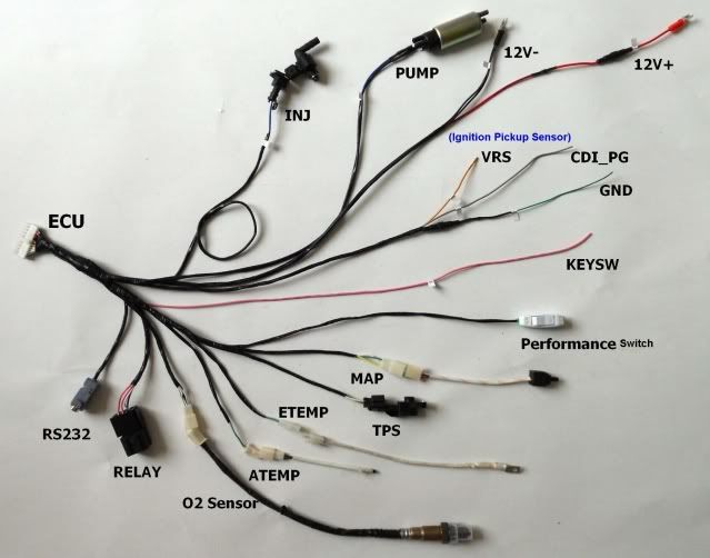 Step 6.1. Identify ignition pickup sensor wire and ground on CDI box Step 6.2. Splice the ignition pickup sensor wire, and connect it to ECU VRS wire (orange wire on harness) and secure the splice.The VCS wire is a variable reluctant sensor wire. Step 6.3. Connect ignition pickup sensor ground to the ground wire (green wire on harness) , if you don't want to use ECU to control CDI go to step 7. ( It is good practice not to use the ECU to control the CDI first, get the engine running then use ECU to control CDI.) If you want to use the ECU to control the CDI ignition timing, and if our 6-pin CDI was included in the kit (I didn't get their CDI in the kit) :cut the ignition pickup sensor wire, and connect the wire on the sensor side to the ECU VRS input (orange wire on harness). Step 6.4. Then connect the other side of wire (the one you just cut) to the ECU CDI-PG (pulse generation), (Gray wire on the harness). (may be called "sensor signal" on CDI connector). Note: if you use the ECU to control your own CDI, it may not work. Note: if you don't know the pin definitions on your CDI connector, DO NOT CONNECT CDI-PG WIRE!! Step 6.3. Secure connections using tape, or solder then tape. Step 6.4. On most CDIs, there are 2 ground wires on the connector and likely only 1 of them is connected to chassis ground. We suggest that you connect the other ground wire to the chassis ground. Step 7. Splice the "key switch" wire, and connect it to ECU "KEYSW" input (pink wire). The "key switch" is the +12V signal coming from the key-on; for some scooters, it also goes through "stop/kill" switch. The splice should be after the "stop switch", or after the "key switch" if there is no "stop switch". This is the ECU power-on trigger. Without thi wire connected, the ECU will not power on. Note: If there is no key-switch, the "KEYSW" wire can be connected to +12V. But you must install a manual switch between +12V and "KEYSW" wire. Step 8. Install the ECU in a safe place (it should be close to the EFI components, for example, under seat or in trunk). Step 9. Connect EFI components to the harness. Step 10. Connect ECU to 12V battery + and battery -. Step 11. Make sure 12V battery - is connected to chassis ground. Step 12. Check to make sure all wires are connected properly. Roy |
|
|
|
Post by royldoc on Apr 24, 2011 12:22:11 GMT -6
I was installing fuel hoses last night and the last clamp in the kit would not tighten up. the screw would turn a few turns then would bind up. So I'm thinking no problem I got some in the shop. Well I searched for some time to no avail . Wouldn't you know it I got every type and size of clamp but what I need. Well I'm wanting to get this project done so I proceed to take the clamp apart and find out why it don't work. I got it apart didn't see anything wrong (clamps are fairly simple devices). I Put it back together and it still don't work, huh. I took it apart again and inspected it under a magnifying glass. the threads on the worm screw were cut all the way to the head causing it to tighten up. I get my files out and clean up the screw around the head. I put it back together and tested it. after several try's I finally got it to work. ;D
Now here is the funny part. I spend hundreds of dollars and many hours modding this scooter and I spent nearly 2 hours trying to fix a .20 cent hose clamp.
Roy
|
|
|
|
Post by royldoc on Apr 24, 2011 11:29:38 GMT -6
Step 5. Install engine temperature sensor. Find a place on cylinder head with the least amount of air flow (usually the backside of engine). I used one of the valve cover bolts (top right in photo).  Step 6. Install intake air temperature sensor. Insert sensor into the air filter or someplace between filter and throttle body. Since my filter is a screen type I poked a hole in it and inserted sensor.I used a zip tie on wire so it would not go in to far. Then I used another zip tie around filter so it would not pull out  Roy |
|
|
|
Post by royldoc on Apr 24, 2011 2:27:34 GMT -6
Here is a diagram of the fuel system.  Roy |
|
|
|
Post by royldoc on Apr 24, 2011 1:56:03 GMT -6
I got the fuel pump and pressure regulator mounted. The correct mounting of fuel supply components are. The fuel injector lower than the fuel pump, the fuel pump and fuel filter must be lower than the lowest part of the fuel tank. My tank has a vacuum petcock. I will need to replace or modify and use a manual valve. I forgot to get manual petcock today so will do that tomorrow. 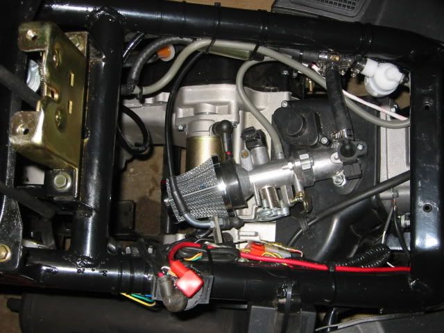 Roy |
|

